4D World (XIV): Irregular Rollings
// Note: Almost all the 4D rolling simulations mentioned in this article can be found in the Tesserxel examples under Physics World -> Irregular Rollings, and you can use T/G/F/H/R/Y to control the objects' rolling.
In 3D space there are some strange rollable things, such as the Oloid, Wobbler, and the Steinmetz solid mentioned in this video by Maker’s Muse. Let us try to analogize them to 4D, and look deeper into the 4D derivatives of the crinds.
Wobbler
 The wobbler can be regarded as the easiest to understand among these strange shapes. It is the shape produced by obliquely cutting a cylinder; both ends are oblique elliptical cylinders, so when it rolls it appears to wobble, and the contact shape really is serpentine. The convex hull of this shape is just a cylinder. When the object touches the flat ground, its concave parts have no chance to touch the ground, so its rolling behaviors are completely the same as those of its cylindrical convex hull.

Spherinder generalization
Generalizing this to 4D gives two cases: the spherinder and the cubinder. The side view of a spherinder is a cylinder. We directly choose the plane in 3D space that cuts out the wobbler, and then span flat cells with the projection direction perpendicular to the side view, so that these cells can cut the spherinder and produce a 4D spherinder wobbler. This thing can likewise be regarded as the solid of revolution of the 3D wobbler about the plane containing the major axes of the oblique ellipses on both sides. You can click here to see the rolling simulation of the 4D spherinder wobbler in Tesserxel.
Cubinder generalization
The spherinder wobbler has 2 rolling degrees of freedom, while the cubinder and duocylinder have 1 rolling degree of freedom, and both of the two 2D directions are extrusion directions. We do not have to make it roll with a one-directional offset like the wobbler mentioned before; we can instead let the contact shape move in a 2D space. At that time I thought: can we make a shape whose contact shape is three circles, and after rolling one full turn the three circular contact shapes have rotated exactly 120 degrees? These three circles are twisted and connected into a whole, so a central axis is no longer needed to connect them. Three circles are not simple or basic enough; we might as well directly consider the rolling of the convex hull of those three circles in 4D shrunk to points. Then the whole shape becomes a kind of torus knot—that is, the trajectory produced when the speed ratio of a double rotation is rational.
At this time the convex hull has two placement modes. The first is a triangular contact shape consistent with the behavior above (corresponding to three circles shrunk to the vertices of a triangle), rolling along a straight line like a cylinder, and during rolling the triangle keeps rotating.  Note that when it rolls, it only performs a simple rotation in the plane spanned by the forward direction and the vertical direction; the triangle is only the contact shape spinning by itself, and the whole object does not rotate. This is similar to the rotational trajectory of the wobbler, and also similar to the rolling of the 4D object polytwister (the intersection of many cubinders, or the convex hull of many Hopf fiber circles).
After placing it on its side there is another rolling mode: after the convex hull is placed on its side, it contacts the ground at only two points, forming a rolling mode similar to that of a duospindle. I think this thing might be treated by 4D-world children as a hoop to roll. Unlike our world’s 3D hoops, it does not easily fall over, and even if it falls, it can continue rolling. 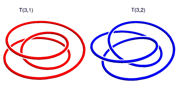
The more general case is that a regular p-gon rolls one full turn and rotates by p/q turns; the trajectory is a (p,q)-torus knot. Just now was the case p=3, q=1, but the trajectory was not knotted. If “coincides after rotating 120 degrees” is changed to “coincides after rotating 240 degrees”, this corresponds to p=3, q=2, and then it is a trefoil knot. The rolling mode of the trefoil knot is the same as before, but once p/q parameters are both greater than 2 and a polygon can be formed, that duospindle-like 2-degree-of-freedom rolling degenerates. For example, for a (3,5)-torus knot, if the side corresponding to the 3-period rotation plane is placed on the ground, the contact shape is a triangle, and as it rolls forward the triangle begins to rotate. Rotate this convex hull by 90 degrees so that the side corresponding to the 5-period rotation plane touches the ground, and the contact shape becomes a regular pentagon; when rolling, the pentagon rolls while rotating. This is almost the rolling mode of a duocylinder—as the name torus knot suggests, it is a knot on a flat torus; when the parameters become complex, the whole shape gets closer and closer to the convex hull of a flat torus, that is, a duocylinder. In an even more extreme case, when the ratio of the double-rotation angular velocities is irrational, all phase combinations on the two rotation planes become densely ergodic, and it completely becomes the rolling mode of a duocylinder.
Sphericon and Oloid

In 3D space, rotating a square about its diagonal as an axis gives a bicone. We cut it in half, then rotate one half by 90 degrees and glue it back, obtaining this shape called a sphericon. Note that it should be distinguished from the 4D sphone. It can also be regarded as the convex hull of two perpendicular semicircles sharing the same center.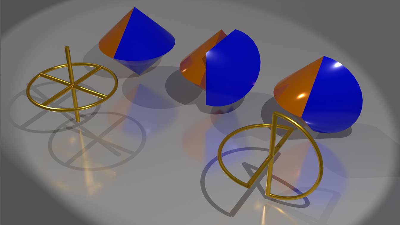
The simplest way to analogize it to 4D is to directly rotate the sphericon about the plane containing one of its semicircles as an axis and lift its dimension to 4D, obtaining a shape with a sphone on one side and a duospindle on the other; their common glued part is a bicone. We can use stereographic projection to mark the spherical surface and cone point of the sphone, as well as the positions of the two circles of the duospindle: 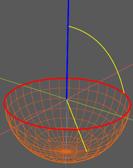 The contact shape of the sphone half corresponds to one endpoint fixed at the endpoint of the blue semicircle (after projection through the pole it becomes a ray), while the other endpoint performs the standard 2-degree-of-freedom sphone-mode rolling freely on the hemisphere. The duospindle half corresponds to a 2-degree-of-freedom motion in which one endpoint slides freely on the red circle and the other endpoint slides freely on the blue circle. Both parts are 2-degree-of-freedom rolling, and their rolling paths have infinitely many possibilities, unlike the 3D sphericon, which has only one fixed rolling path.
There is another geometric body called the Oloid. It is the convex hull of a linked pair of rings, in which two circles are perpendicular, and the center of one circle lies exactly on the circumference of the other:  After taking the convex hull, only 240° of arc of each circle remains outside, and the remaining 120° is enclosed inside. Its rolling is not easy to understand, but its rolling mode is similar to that of the sphericon, while its appearance is rounder and lacks the sharp cone points of the sphericon. When it rolls it also looks somewhat like the wobbler rolling serpentinely on the ground; the figure swept out by its contact shape on the ground looks like this:
 This thing also has some special uses in mechanics; see this video for an incredible Oloid mixer with a unique shape that can save energy.
The Oloid can naturally be lifted to 4D by rotation into the convex hull of a sphere-circle chain, that is, the solid of revolution obtained by choosing a circle as the plane axis. Apart from this crude method of rotational dimensional lifting, are there other possibilities? For the Oloid, its definition is too special, and I have not yet thought of another 4D analogue, but for the sphericon we can still struggle a little. The previous rotational dimensional lifting method gives 2-degree-of-freedom rolling. If we give up one degree of freedom, the sphericon still has more 4D analogues.
More complex Sphericons
The 3D sphericon also has some variants, such as the hexagonal sphericon, which is the product of rotating a regular hexagon about a diagonal, cutting it, rotating and offsetting it, and gluing it back. Besides diagonals, symmetry axes of polygons can also be lines joining midpoints of opposite sides. Rotating about such a line makes the side containing the midpoint form a flat circle, which cannot roll in contact with the ground like other conical surfaces. The figure on the left below is obtained by rotating a square about the line joining midpoints of opposite sides, cutting, twisting by 90 degrees, and gluing, i.e. a shape made of two half-cylinders glued together. It can be seen that the semicircle is the endpoint of rolling, so when designing a sphericon one should try to avoid line segments completely perpendicular to the rotation axis. In addition, other shapes with regular-polygon symmetry can also make sphericons, such as the gear-shaped thing below; of course, its rolling is the same as that of a regular octagon (middle figure below). 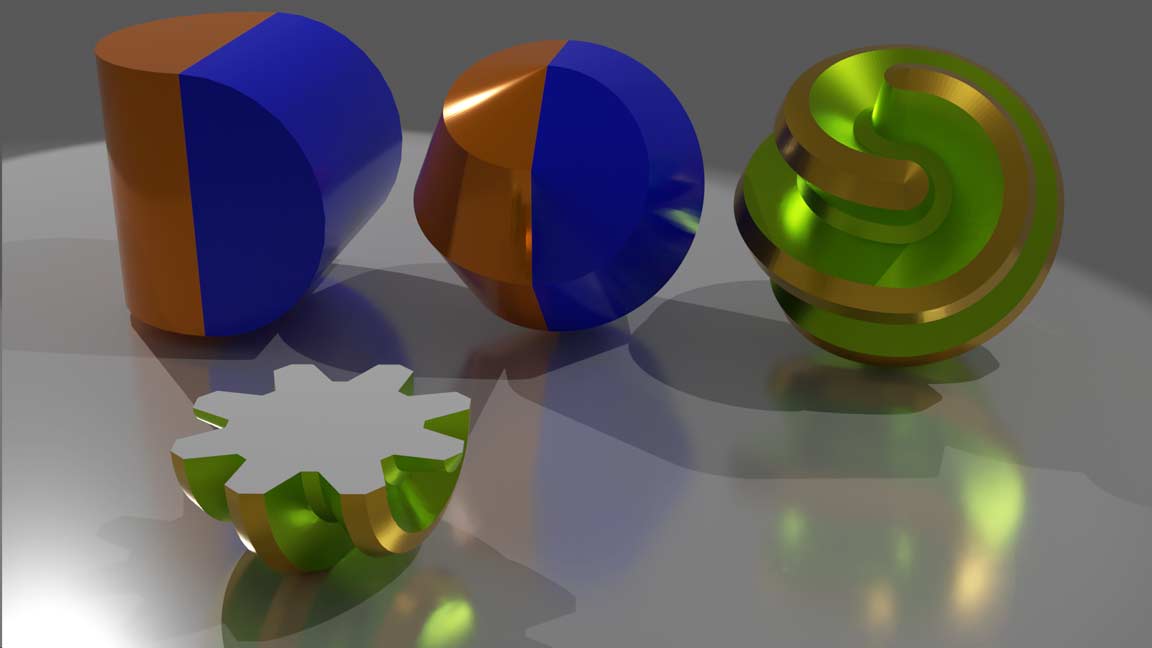 In 4D one can choose a regular polyhedron, rotate it by 360° about some rotation plane, cut it into two halves, then rotate the rotation plane to another position and glue it back. I envisioned the “Hypersphericons” of the five regular polyhedra and marked the positions of the rotation planes of the two halves. For the cube, rotating its diagonal plane actually gives the two half circular duospindle cylinders rotated and glued together; for the regular tetrahedron, it is two half dicones rotated and glued together; for the regular octahedron, it is two half bicylindrone rotated and glued together; while the 4D objects corresponding to the regular dodecahedron and icosahedron are too complex, but they can be obtained by Boolean operations from some basic circular prismatic / pyramidal combinations. Can these shapes roll continuously? Readers are encouraged to think about it first.
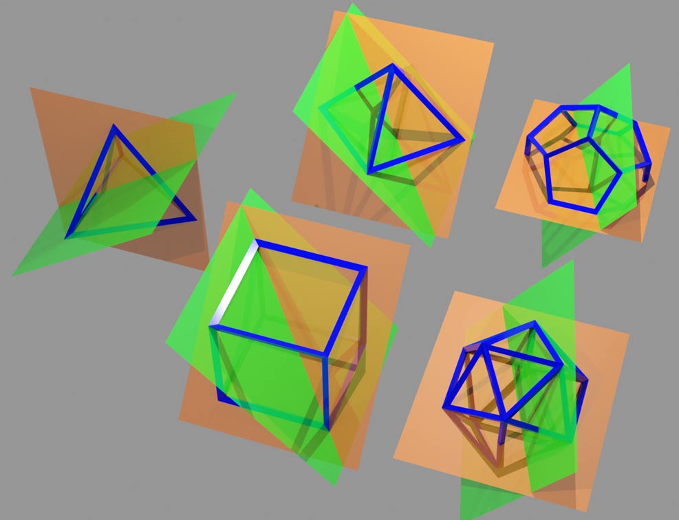
We can analyze in the figure above: after rolling 180°, the surface contacting the ground rotates to the mirror-image position on the other side of the plane axis, and then it switches to rotating 180° about the other rotation plane axis, mirroring again… When the object rolls, the contact shape is alternately reflected in the view above by the two planes, and two cases arise:
- The whole reflection forms a cycle, meaning the object can roll indefinitely, similar to the simplest sphericon that rolls continuously and meanderingly along the diagonal of a rhombus;
- A situation appears where the plane containing the contact shape is perpendicular to the plane axis; then this face is no longer a conical surface, and the object can only reverse when rolling there, similar to the case of the square rotated about the line joining midpoints of opposite sides.
Let us change our viewpoint and look along the intersection line of the two planes; then these surfaces are equivalent to rotating and reflecting about the center with regular-polygon symmetry. Mark the faces perpendicular to the rotation plane; they will be reflected to other symmetrical positions, and after these positions touch the ground they cannot roll continuously. Only faces that will never become perpendicular to the rotation plane axis no matter how they are reflected can keep rolling smoothly all the time. After analyzing the five shapes one by one, the answer comes out: the highlighted surfaces are perpendicular to some plane and cannot roll; the planes with red arrows are not perpendicular, but will rotate to a perpendicular plane as rolling proceeds; after switching axes they cannot roll continuously; green arrows form closed loops that can roll continuously. 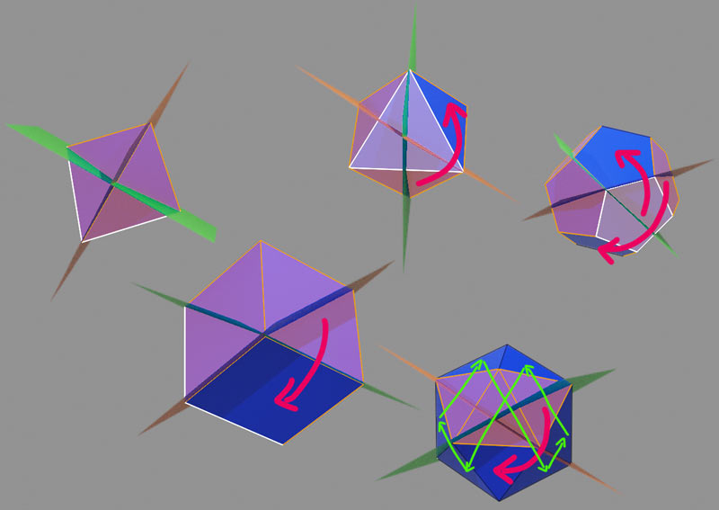 The conclusion is: among the five shapes above, only the icosahedral sphericon can roll continuously. The example in Tesserxel already places the icosahedral sphericon by default in a way that allows it to roll forever. Switch the view to horizontal cross-section mode and adjust the camera height to just a little above the ground, and you can see that the contact shape is a triangle with some thickness, constantly moving and rotating; the trajectory is a drifting spatial curve, very beautiful. This triangle is somewhat dark because the horizontal cross-section captures pixels at the bottom of the object in the 3D voxel image, where the lighting is naturally darker.
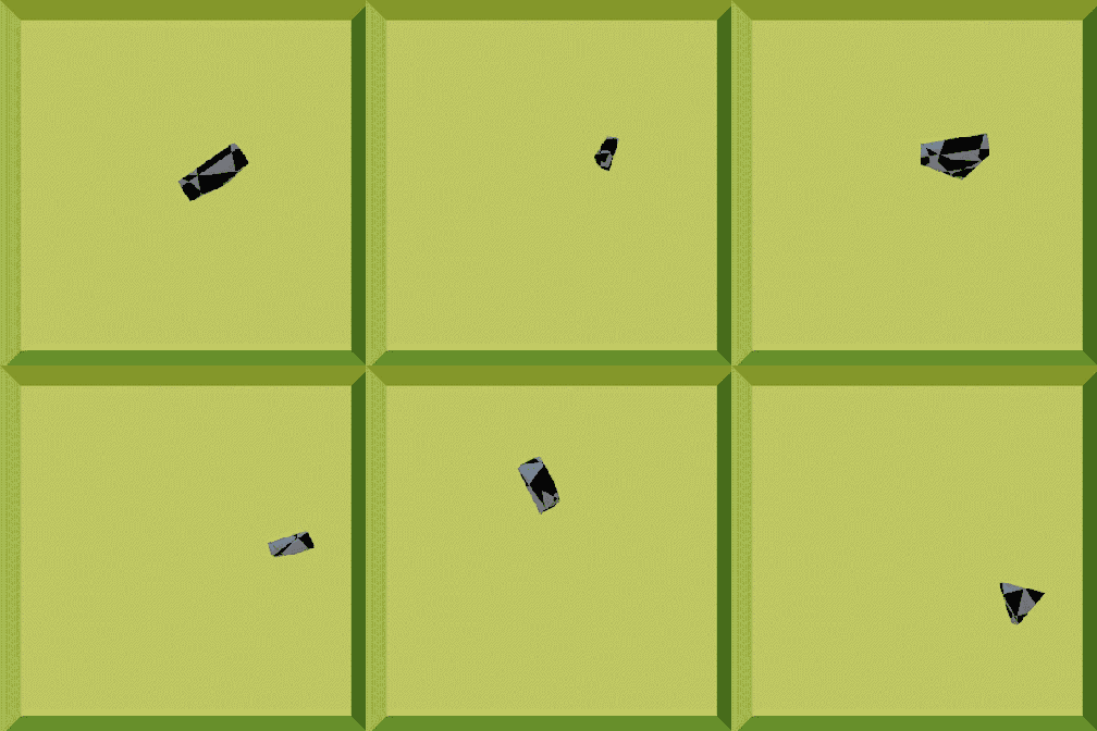 Seeing this, one cannot help asking: what pattern is the trajectory of its center of mass? Is the whole trajectory a closed curve? Obviously they are many circular-arc paths pieced together by the rolling of coninder surfaces, but calculating the specific arc lengths and angles is somewhat tedious; this problem is left to interested readers.
It is worth noting that the rotation planes of the five regular polyhedra are not necessarily only the choices I made here. All choices can be classified by whether the intersection line of the two planes passes through a vertex, an edge center, or a face center. In this way each regular polyhedron has three different sphericons (actually, for the regular tetrahedron the vertex and face-center choices are equivalent, so some figures still need to be excluded). Perhaps other shapes that can roll continuously can also be obtained.
Crind
The crind was first used by an ancient Chinese mathematician to calculate the volume of a sphere. It is naturally defined by cross-section animation: the cross-section animation of a sphere is a circle that first grows and then shrinks according to the size variation rule of cutting a circle; the crind is a square that first grows and then shrinks according to the size variation rule of cutting a circle. The cross-section animation also shows that it is the intersection of two perpendicular equal cylinders: extending the four sides of the square reveals the cross-section animation of these two cylinders: This is so called Steinmetz solid. 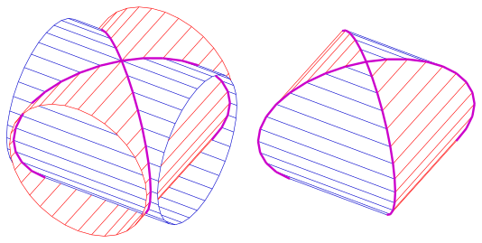 crind and Steinmetz solid are different. Let us understand them from the viewpoint of the convex hull: the crind can be regarded as the convex hull of two circles in the xy-plane and the yz-plane. But the definition of the Steinmetz solid is the intersection of two equal perpendicular cylinders; its edges (the purple circles in the figure above) are actually two perpendicular ellipses with major-to-minor axis ratio $\sqrt{2}$, not true circles. Strictly speaking, therefore, the Steinmetz solid is the convex hull of two perpendicular ellipses. If one directly uses true circles to make the convex hull, the surface instead becomes elliptic cylindrical surfaces. Since the center of gravity changes when an ellipse rolls, it can no longer roll continuously and smoothly, so special care must be taken with this scaling relationship when rolling is involved.
The crind has two cylindrical surfaces. When rolling, generally only one surface contacts the ground and it rolls like an ordinary cylinder, but there are two special points where the two cylindrical surfaces not only intersect but also have coincident tangent planes, meaning that at this position one can choose to switch to the other perpendicular direction to roll. From the structure of its contact shape on a 2D table, one can see that the contact shape at this intersection point is a very small square; at this time one can roll in either of the two directions of the square, and after choosing one direction, the perpendicular direction becomes longer. 
Next let us analogize the crind to 4D.
Cubic Crind
The crind has at least three ways of understanding: the cross-section method, the intersection method, and the convex-hull method. Therefore there are very many 4D generalizations of the crind. The simplest is the cubic crind. It corresponds to a cube that first grows and then shrinks according to the circle-section rule. Can it also be regarded as the intersection of some cylinders in 4D space? The answer is yes. Extend the six faces of the cube; in the cross-section animation every two parallel planes form a cubinder, so the cubic crind is the intersection of three cubinders oriented in the xy/yz/xz planes. In fact it can also be said to be the intersection of duocylinders, because as long as the other circle of the duocylinder is large enough it does not affect its intersection behavior with other objects. When cubinders are mentioned as intersecting later, they can by default be replaced by duocylinders.
What shape’s convex hull is the cubic crind? Since the cross-section animation is a cube growing and shrinking, we only need to grasp the eight vertices that support the cube. Since the size is scaled according to the circle-section rule, the trajectories of the eight vertices are all circles, but a bunch of vertices on the body diagonal are actually on one circle, so the cubic crind corresponds to the convex hull of four circles. In fact, the convex hull and the cross-section animation have a relationship: the convex hull of a cross-section animation equals the cross-section animation of the convex hull.  The cubic crind rolls similarly to a cubinder/duocylinder; it can only roll in one direction, and when it rolls to the intersection point of the three cubinders (i.e. the brief pause moment in the animation above), there are 6 rolling directions to choose from: positive and negative x/y/z axes. At this point the contact shape is a small cube; whichever face direction one rolls toward, that face becomes larger, and the whole contact shape becomes a thin square sheet.
Octahedral Crind
Besides the cube, the square can also be generalized along the cross-polytope route to the regular octahedron. The octahedral crind is a regular octahedron that first grows and then shrinks according to the circle-section rule. Since the regular octahedron has 4 pairs of parallel planes, combining this with the cross-section animation shows that it is the intersection of four cubinders. What shape’s convex hull is the octahedral crind? Similar analysis to the cubic crind shows that it is the convex hull of three perpendicular circles—that is, the convex hull of the unit circles in the xw/yw/zw planes. The rolling degree of freedom of this thing is also 1, and its contact shape is generally a thin regular triangle. As it rolls toward a special point, the triangle begins to shrink. Considering the thickness of the contact shape, the side near the special point shrinks first; the contact shape is actually a triangular frustum, and finally the triangle on the side near the special point first shrinks to a point, then becomes an inverted triangle. When the object’s center finally lands on the special point, the contact shape is a regular triangular antiprism, exactly becoming a perfect regular octahedron. At this time there are 8 (4 pairs of) different rolling directions to choose from. 
Cylindrical Crind
It is getting more and more abstract. What can the cylindrical crind be regarded as the intersection of? Please think about it first, and we will reveal the answer shortly. As for the convex hull, it also has 2D edges similar to those of a duocylinder, that is, it is the convex hull of its own edges, but these 2D edges are rather complex and not easy to regard as a simpler basic shape. The rolling of the cylindrical crind is actually quite interesting. The first thing one can think of is the conic frustum contact shape similar to that of the regular octahedron and cube crinds:  Interestingly, after passing a special point one can choose to have the cylindrical base touch the ground or the side surface touch the ground; what was just described was only the case with the base touching the ground. The case with the side surface touching the ground becomes more complex: the crind itself is curved like a circle in one direction and can roll, while the cylindrical surface itself is also curved. Perhaps at this time the rolling degree of freedom of the object rises from 1 to 2? We had better figure out what shape it is obtained by intersecting in order to understand its rolling properties: suppose the base circle of the cylinder of the cylindrical crind is parallel to the xy-plane and its height is along the z-axis. From the cross-section animation along the w-axis, one can see that it is the intersection of a cylinder that becomes thicker and thinner and a plane that becomes thicker and thinner, showing that it is the intersection of a cubinder in the xy-plane direction and a spherinder in the z-axis direction. The cubinder and spherinder exactly correspond to two rolling modes, and the degrees of freedom also match.
 In spherinder mode this contact shape can move in any direction perpendicular to the left-right direction, corresponding to 2 degrees of freedom. At the special point the contact shape becomes a cylinder, and it can also move left and right, becoming the previous conic frustum mode.
Dicrind
The next shape should originally be called “crindrical crind”; such nesting is too awkward, so we call it the “dicrind”. As the name suggests, its cross-section animation is a crind that grows, shrinks, and disappears according to the circle-section scaling rule. This thing is obtained by intersecting two spherinders: it is known that the crind is the intersection of two cylinders. Adding that kind of growing-and-shrinking cross-section animation shows that it is the intersection of two cylinders that simultaneously become thicker from thin and then thinner and disappear, which is the typical cross-section animation of two spherinders. Why does a sphere appear in the dicrind? In one sentence: “the circular crind is a sphere.” The crind can be understood as something square in the xy direction and circular in the z direction. Now the w-axis “crinds” it once more, giving a shape that is square in the xy direction and circular in the zw direction. Note that this thing is not the convex hull of an absolutely perpendicular square and circle (that is, a 4D circle–duospindle); the convex hull is diamond-shaped in the middle xz/yz/xw/yw planes, while the dicrind is circular in these planes. In fact it is the convex hull of two perpendicular spheres with the same center; for example, if the two spheres lie respectively in xyz/yzw space, then viewed in the xw-plane it is square, and viewed in the yz-plane it is circular.
The rolling of the dicrind is also rather abstract. It is the convex hull of two perpendicular spheres with the same center. When this thing is placed on the ground, its two ends produce tiny circular contact shapes of a spherical surface resting on a table. This is very similar to the rolling of the cylindrical crind with its side surface on the ground, except that the tiny shape of the contact shape near the special point differs somewhat. Let us put the previous figures here for comparison:  This similarity has a reason: the dicrind is obtained by intersecting two spherinders, while the cylindrical crind is obtained by intersecting a spherinder with a cubinder. Both spherindrical surfaces are placed on the ground and rolled, the behavior is naturally very similar. The dicrind also has an interesting property: its special points are no longer isolated points; their set is an entire 1D circle, and this circle is exactly the intersection circle of the two perpendicular spheres with the same center. At the special points, the dicrind has three rolling directions to choose from: two directions make the two circles of the crind separate and become a rod-like contact shape similar to a cylinder, while the third perpendicular direction keeps the contact shape in the shape of a crind, i.e. rolling continuously along the special circle, with the object always at the special point.
Circle–sphere convex hull and solids of revolution
In 3D space the convex hull of two perpendicular circles is the crind. In 4D one can place a circle in the xy-plane and a sphere in yzw space and take the convex hull. It is also a kind of crind. Please guess what 3D shape is crinded to obtain it; the answer will be revealed shortly. It can also be explained from the viewpoint of a solid of revolution: taking the plane containing any purple circle in the figure below as the axis and rotating the crind also gives the circle–sphere convex hull just mentioned. 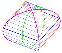 The crind also has two other rotational dimensional-lifting methods: one is to choose the plane containing the largest blue square in the figure above as the axis and rotate; then both cylinders are rotated into spherinders, i.e. the previously mentioned dicrind, producing no new shape. The other is to rotate about the plane containing the green circle in the figure, and the resulting shape is actually also a kind of crind mentioned long ago; this is likewise left for readers to think about.
Starting from the solid of revolution about the plane containing the purple circle in the figure above, we can obtain another explanation of the circle–sphere convex hull: from the rule the solid of revolution of a cross-section animation equals the cross-section animation of the solid of revolution, this solid of revolution is equivalent to the crind of the solid of revolution of a square rotating about its diagonal (i.e. a bicone—two inverted cones). Therefore this convex hull of a circle and a sphere is actually the biconic crind. The biconic crind is currently the only one that cannot be generated as an intersection of cubinders or spherinders, because its surface is generated by rotating a cylindrical surface inclined at 45° about the rotation plane axis; it is something between a spherinder side cell and a duocylinder side cell (i.e. a cubinder side cell). It has rolling behaviors of both cylinder and cone. Personally I think it is actually simplest to explain it as the convex hull of a sphere and a circle half-perpendicular to it.
Next let us reveal the shape obtained by rotating the crind about the plane containing the green circle:
- From the rule the solid of revolution of a cross-section animation equals the cross-section animation of the solid of revolution, the solid of revolution of the crind equals the crind of the solid of revolution of a square. The solid of revolution of a square is a cylinder, so this shape is the cylindrical crind;
- Directly look at what the surfaces become after rotation: the cylindrical surface containing the blue line segment becomes the side surface of a duocylinder after rotation, locally equivalent to the side surface of a cubinder; while the cylindrical surface containing the red line segment becomes a spherinder surface after rotation, showing that this thing is jointly bounded by cubinder side cells and spherinder side cells, which is obviously the cylindrical crind.
Now let us look at the most abstract rolling of the biconic crind. It has two rolling degrees of freedom:
- Since in 3D space the rolling of a bicone is the same as that of an ordinary cone, place the biconic crind on its side so that the middle “waist” touches the ground. At this time, as long as one does not roll toward the crind caps, its rolling mode will be like that of a coninder: the circle and sphere in the convex hull produce a small line segment and a small circle contact shape at the two ends respectively, and the coninder rolling mode makes the whole contact shape roll while rotating about the small chord segment where the circle lies.
- It can also start from the middle “waist” touching the ground and roll toward a special point. This is the rolling degree of freedom given to it by the circular nature of the crind, and the mode is more like a general 1-degree-of-freedom rolling cylinder: the whole contact shape translates toward the common direction of the line segment and the circle. However, after leaving the “waist” position, the line segment and the circle are no longer parallel; their distance continuously decreases and the angle increases, until finally the distance shrinks to 0 and the angle becomes perpendicular. The contact shape becomes a bicone, and the whole shape reaches the special point. At this time it can roll in the direction perpendicular to any generatrix on the conical surface.
 I can only infer that the cone rolling mode is quite stable and smooth when the middle “waist” touches the ground, but when it leaves the middle waist and rolls toward the special point to an intermediate position, the circle and the small line segment are inclined. Can the cone rolling mode still be smooth? I admit I simply cannot figure it out, but fortunately the Tesserxel physics engine comes to the rescue. The result is that it can still rotate and roll smoothly, except that each rotational roll spontaneously superimposes some translational rolling. I am not sure whether this is because I did not align it during simulation, causing a velocity component of translational rolling, or whether the geometric properties of this thing really convert oblique rotational rolling into translational rolling. I guess the latter is more likely:
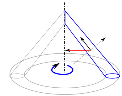 Since this rotation is about the line-segment contact shape at one end as an axis, purely rotational rolling should in principle sweep the whole contact shape into a conical surface. But one component of the centripetal force required for rotation (the red force in the figure) is exactly the direction of translational rolling (the gray dashed line direction). In this direction friction naturally cannot be provided, and finally only friction in the black arrow direction provides the centripetal force. Inertia therefore makes the object not obediently rotate and roll along the conical surface; it throws the object off the conical surface along the gray dashed line, naturally giving it a velocity component of translational rolling in this direction. Moreover, this translational rolling direction always makes the object roll away from the special point, consistent with the simulation results in the Tesserxel engine.
Intersections of multiple cylinders
In 3D space, the intersection of three mutually perpendicular solid cylinders of the same radius has the combined structure of a rhombic dodecahedron, but each “face” is a cylindrical surface patch rather than a flat rhombus. Three perpendicular cylinders are equivalent to forming a symmetric structure passing through all face centers of a cube (or, equivalently, all vertices of a regular octahedron). What about other regular-polyhedron symmetries? Paul Bourke’s website lists the intersections of cylinders with all regular-polyhedron symmetries in 3D space: 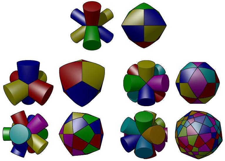 The natural question is: previously our cubinders/spherinders were arranged only according to cube/square symmetry. If arranged according to the symmetry of a tesseract or other regular polychora, what will the skeleton of the middle shape look like? Specifically:
- Line-like spherinders: place spherinders on the lines connecting each vertex of the regular polychoron to the body center, and take the intersection;
- Face-like cubinders: place cubinders on the planes spanned by each edge of the regular polychoron and the body center, and take the intersection.
There are six regular polychora in 4D, corresponding to 12 intersections in total. This problem looks too difficult. The first thing I thought of was to use the symmetry of the regular polychoron and, like blind men feeling an elephant, analyze only the situation at special positions to feel out the whole shape. For example, derive the intersection of three mutually perpendicular cylinders in 3D space called tricylinder: 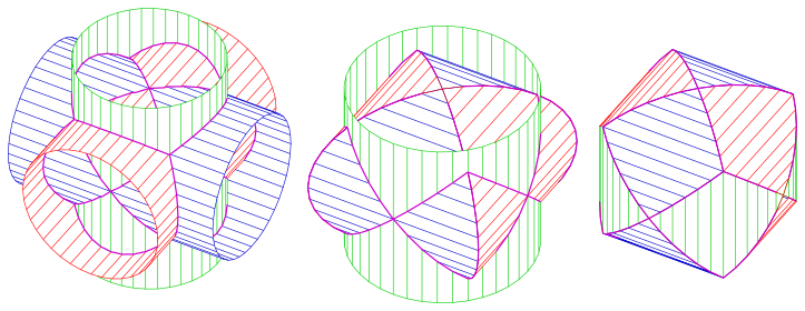 Let the three cylinders along the coordinate axes have radius 1. It has cube/octahedron symmetry. Let the cube vertices have coordinates $(\pm 1,\pm 1,\pm 1)$. We use some rays through the origin at special symmetric positions to probe this intersection:
- In the cube-vertex direction, let the intersection point of the ray with the object be $(a,a,a)$. Its squared distances to the three cylinder axes are the same, all $2a^2$, so this is a vertex, with coordinates satisfying $2a^2=1, (a,a,a)=(1/\sqrt2,1/\sqrt2,1/\sqrt2)$.
- In the cube-edge-center direction, let the point be $(a,a,0)$. The $x$/$y$ two cylindrical surfaces intersect at $(1,1,0)$, but the $z$-axis cylinder only needs to reach $(1/\sqrt2,1/\sqrt2,0)$ to reach the boundary, closer to the origin; the intersection takes the innermost layer. Note that only the $z$-axis cylinder participates in the innermost layer, so the edge-center direction corresponds to the interior of a surface patch, equivalent to the face center of the dual polyhedron.
- In the cube-face-center direction, let the point be $(a,0,0)$. It lies completely on the $x$-axis, i.e. inside the $x$-axis cylinder, and can be ignored; the other two cylinders intersect here at a vertex, i.e. the special point of the crind.
In summary, the tricylinder has degree-3 vertices in the cube-vertex directions, degree-4 vertices in the face-center directions, and surface-patch interiors in the edge-center directions (face centers of the dual polyhedron). Only the rhombic dodecahedron fits. The two types of vertices of the rhombic dodecahedron differ greatly here: at the cube vertices there are truly protruding corners, while at the face-center special points it is flat. Because special points exist, during continuous rolling all surfaces of the tricylinder have a chance to contact the ground, but the rolling degree of freedom of the object is 1. The set of places that the projection of the center of mass onto the object’s surface can reach during rolling is the red, green, and blue three circles in the figure below; their intersections are naturally the special points: 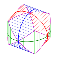
Extending this method to 4D can derive the case of four spherinders intersecting along the coordinate axes and six cubinders intersecting on the coordinate planes, but the derivation process is both tedious and unintuitive. Readers can click here to expand the derivation process. This process is less a derivation than a correct guess through symmetry, and for other regular-polychoron symmetries not on coordinate planes, deriving by substituting special positions is even more tedious. A more efficient and direct analysis method must be found.
Exploring the pattern
Besides studying the regular-polyhedron cases, Paul Bourke also tried choosing many randomly oriented cylinders to intersect, and found that not many cylinders are needed before the intersection very closely approaches a sphere. The pattern on this spherical surface caught my attention: the same cylindrical surface may be divided into very many regions, but they are all connected through special points into a large circular ring; here lies the rule governing the surface structure. Draw all the great circles where the normal planes of the cylinder orientations intersect the sphere, and let every point on the sphere “claim” the nearest great circle; dividing the whole sphere in this way, forming something like a Voronoi diagram, gives the result of these cylinder intersections. At the same time, these great circles are also the trajectories of the center-of-mass projection during rolling, and the intersections between great circles are the special points where the rolling direction can be switched. 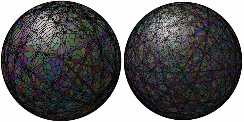 This example shows that sometimes one should not first understand the simplest shape and then understand more complex shapes; the order may be exactly the opposite—only when the shape is complex enough does the pattern show itself better.
Spherinders intersecting along coordinate axes
In 4D space the extrusion direction of a spherinder is 1D, and its normal space intersects the hypersphere in a sphere. If the spherinders are all along coordinate axes, these spheres will naturally be drawn on the coordinate cells perpendicular to the axes, i.e. there is a great sphere on all four coordinate cells. It can be seen that the trajectory of the center-of-mass projection when this intersection shape rolls is exactly these four spheres, i.e. the structure obtained by inflating the 2D faces of the 16-cell onto the hypersphere, which exactly matches the 2 degrees of freedom of spherinder rolling. All edges of the 16-cell, i.e. the circles obtained by intersecting the spheres, are special points; here one can switch direction to go to a different sphere, and the rolling behavior is equivalent to the special points of the dicrind. 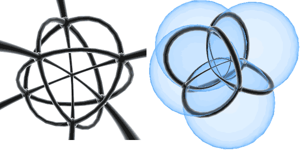 Other points on the hypersphere are divided by the nearest great sphere; the centers of these regions are naturally at each face center of the 16-cell, and by duality are also equivalent to the edge centers of the tesseract. This figure may be somewhat abstract, but its dual polytope has all vertices at edge centers and is clearly the rectified tesseract. According to the vertex figure of the rectified tesseract, the overall frame shape of this intersection is a 4D polytope bounded by 32 congruent triangular bipyramid cells.
In Tesserxel I drew the interwoven structure of the four spherinder surfaces from a viewpoint similar to stereographic projection. In the figure below, left and right are naked-eye 3D and can be ignored if you cannot view them; top and bottom are two 3D views of the same voxel image: the yellow region is a certain spherinder cell. After taking the intersection, it is divided into 8 parts in the first row, 4 of which are in the picture, while the outer 4 are near the projection pole and cannot be displayed in the voxel image. Combining with the second row, one can see that each part is a triangular bipyramid whose center is at the edge center of the tesseract frame. The edges of the tesseract have four perpendicular directions, exactly divided into 4 groups, each group corresponding to 8 triangular bipyramids belonging to one spherinder surface.  From the first row one can also see that the eight triangular bipyramids separating the same spherinder surface are separated by three perpendicular circles. These circles are obtained by intersecting spheres, so they are all special points; they pass through the face centers of the tesseract, consistent with the previous analysis. The projection of the circle centers of mass can never reach the two apexes of the triangular bipyramid, i.e. the vertices of the tesseract; here, as with the 3D crind, it protrudes.
Cubinders intersecting on coordinate planes
For a cubinder, its extrusion direction is 2D, and the plane absolutely perpendicular to the extrusion direction intersects the hypersphere in a circle. These circles naturally all lie on coordinate planes, so the trajectory of the center-of-mass projection corresponds to the circles forming all edges of the 16-cell inflated to the hypersphere. At the same time, points on the hypersphere are divided according to the nearest circle; each edge center of the 16-cell becomes the center of a region, and by duality the face centers of the tesseract are the centers of the regions. Such a figure is the structure of the regular 24-cell. The 24-cell is originally a highly symmetric figure; the cell centers and vertices of the original tesseract are both vertices of the 24-cell, and they no longer differ in any way. However, the intersection produced by cubinders has a frame resembling the 24-cell but is not so symmetric: the cell centers of the original tesseract are equivalent to the special points of the cubic crind, but the vertices of the original tesseract are truly protruding vertices. 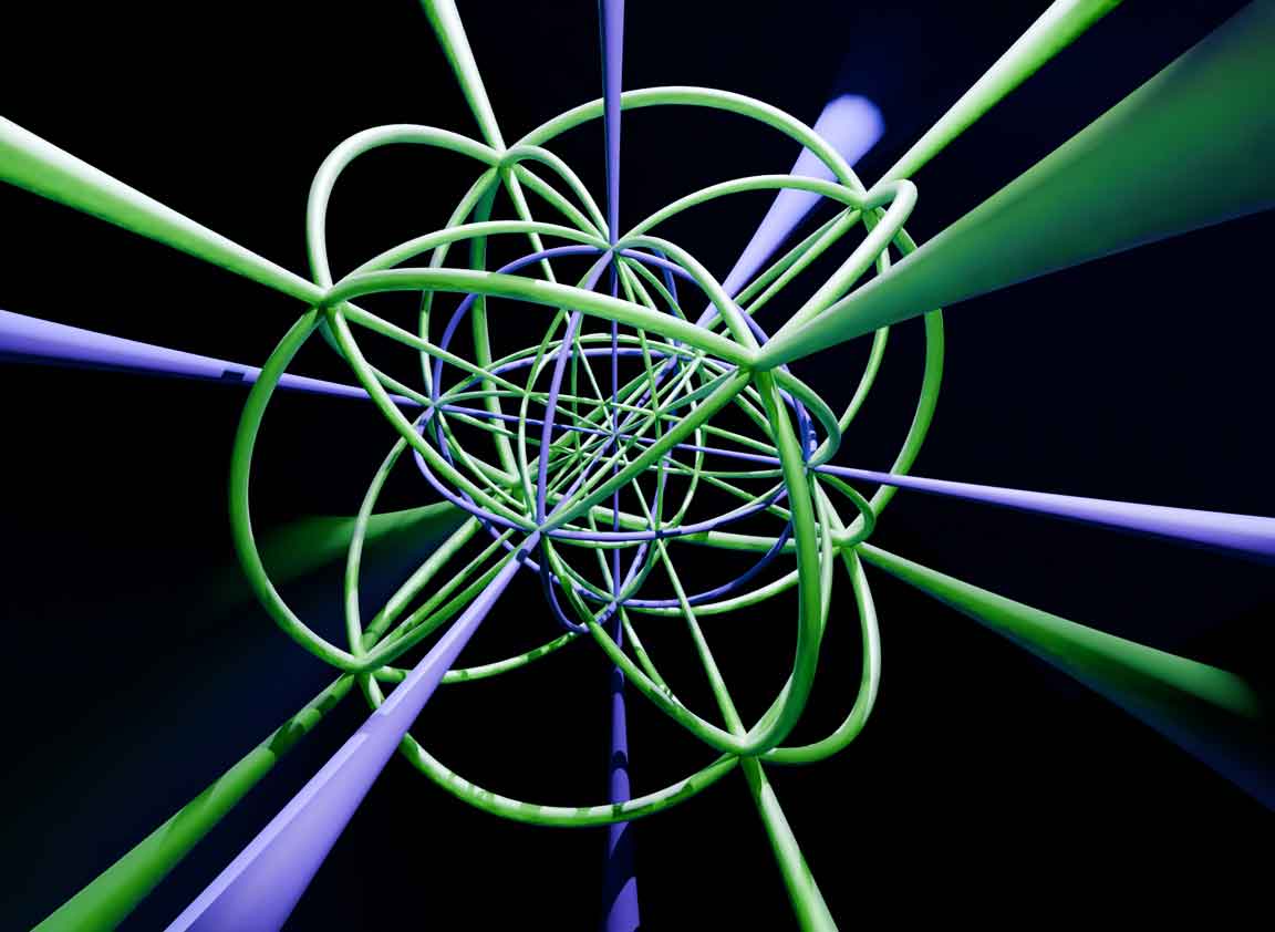
Duocrind
Have we now finished all the typical 4D analogues of the crind? No. Similar to the ditorus and tiger / duotorus, since there is a dicrind (crindrical crind), there is also a thing called the “duocrind”. Before concretely constructing it, let us first take a quick look at how its contact shape changes during rolling: from the contact shape one can guess its rolling degrees of freedom, the positions of special points, and the corresponding selectable rolling directions.  It is the product of intersecting the four cubinders on the xz/xw/yz/yw planes. Why choose the combination of the remaining 4 planes after deleting the two absolutely perpendicular planes from all 6 coordinate planes? Systematically understanding the duocrind requires some new methods for constructing figures: brakectopes and brick products. These contents belong to 4D geometry rather than 4D-world physics, so we will talk about them next time.
Summary of rolling modes
It is time to summarize the rolling modes of so many rollable shapes. First look at the simplest solids of revolution with a single degree of freedom. In a solid of revolution, the cell contacting the ground is generally generated by rotating a plane. Classify by its positional relationship with the rotation plane axis:
- The contact plane is perpendicular to the rotation plane axis: after rotation this face gives a flat 3D cell, which cannot roll.
- The contact plane is parallel to the rotation plane axis: after rotation this plane gives a cylinder, such as a rectangular face rotating to give a cubinder, or a circular face rotating to give the side surface of a duocylinder. They all have 1-degree-of-freedom translational rolling. The most general case is that any 4D shape obtained as the direct product of an arbitrary 2D figure with a circle can roll like a cylinder.
- The contact plane is inclined to the rotation plane axis: after rotation this plane gives a cone. Although cylindrone, coninder, and dicone are different shapes and their contact shapes touching the ground differ, their rolling modes are actually the same.
Cones and solids of revolution
What is the rule for the contact shapes of cylindrone, coninder, and dicone? In fact, if the contact shape of a cone is known, the corresponding solid of revolution can be found. Let us first look at the 3d cone: its contact shape is actually an oblique generatrix on the conical surface; the rotation axis of the whole object forms an angle with the ground, causing the circumference of the base circle to be smaller than the circumference of the contact shape circle it rolls out. The 4D dicone and cylindrone can both roll; their contact shapes are both triangles, but the positions of the axes differ. Let us try to draw their side views containing the rotational symmetry plane. Similar to the side view of a cone, this view compresses out the rolling direction of the contact shape. After introducing the vertical direction, we can observe that as solids of revolution these cones are all the region swept by the contact shape when projected onto the rotation plane axis. In the figure below, the parts of the dicone and cylindrone that can contact the ground are marked light red; their plane axes as solids of revolution are blue, and the rotation axes of the contact shapes on the 3D table are red dashed lines. 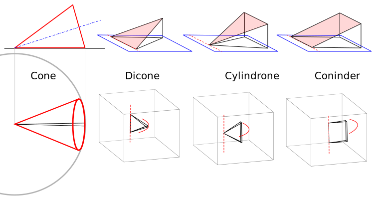
In fact, through solids of revolution we can also obtain some interesting conclusions. For example, the rightmost coninder can be cut along the diagonal of a rectangle into a cylindrone and a dicone, but note that the cross-section of this cut is a right triangle perpendicular to the rotation axis; the actual cylindrone and dicone are separated by a conical cell.
The most general 4D conic rolling, like duocylinder rolling, can freely choose the shape of the contact shape, but in many cases the rolling is more like a conic frustum than a cone. For example, here is what I call the duocylindrical frustum: the solid of revolution of an obliquely cut cylinder about its base. When placed on the ground it has two rolling modes: one is the conic mode, and the other is the straight-line rolling mode as a cylinder, corresponding respectively to the oblique cut surface of the cylinder touching the ground and the side surface of the cylinder touching the ground. In conic mode, its contact shape is an ellipse rotating about an axis outside the ellipse, sweeping out a torus-like shape on the 3D table; in cylindrical mode, its contact shape is a thin disk, but the radius of the disk continuously fluctuates as it rolls, similar to the rolling of the 3D object below. However, as in the 3D case, the center of gravity of this object cannot remain unchanged, so it cannot roll smoothly and continuously, and finally it stops at the position where the side with the largest size touches the ground.  This thing has two rolling modes because the object being rotated itself happens to have a cylindrical rollable surface. If it is replaced by a quadrangular prism, giving a circular-square frustum, then only the cone rolling mode corresponding to the oblique cut surface remains. If the edges of the oblique quadrangular prism are parallel to the tilt direction, the circular-square frustum is actually a circular frustum cylinder.
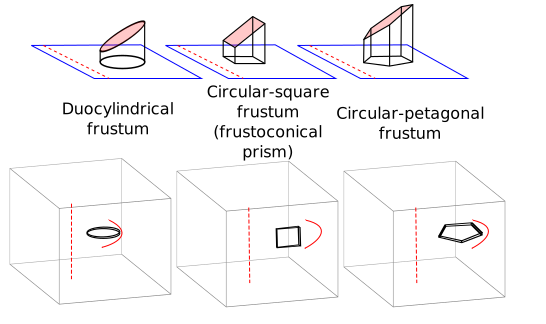 There is another way to make the duocylindrical frustum angular: reduce the step size of the operation constructing the solid of revolution of the duocylindrical frustum, turning it into a polygonal approximation, and obtain something I called square-conical frustum. It is no longer a solid of revolution, but can be regarded as the convex hull of four ellipses, where the major axes of the four ellipses are the oblique edges of the square-conical frustum, and the minor axes are perpendicular to the 3D space containing the square-conical frustum. If the ratio of major to minor axes is appropriate, their side surfaces can be standard cubinder surfaces, very similar to the case of the cubic crind.

The square-conical frustum also has a strange limiting shape, I called it square-conical cone. At this time the four ellipses are tangent at a single point at the cone apex. Similarly, the duocylindrical frustum also has a duocylindrical cone. This position is also a kind of special point: although it looks somewhat like the special points of the cubic crind or cylindrical crind, this is an unstable point: that is, after rolling here one can switch to motion in the perpendicular direction, but in the other direction the object no longer rolls but flips to a lower-energy state, similar to the special point of the 3D figure below. The rolling simulations of these shapes can all be found in the Tesserxel engine example library under Physics World -> Irregular Rollings. 
Multi-DOF rolling modes
For single-degree-of-freedom rolling modes, there are actually only two kinds: cylinder and cone. What about multiple degrees of freedom? The surface of a 4D object is 3D, so the maximum number of degrees of freedom is 3, corresponding to the rolling mode of the hypersphere(glome). The hypersphere is the only perfectly smooth rollable shape; other ellipsoidal hyperspheres also have 3 degrees of freedom, but their center of gravity changes during rolling, causing the object eventually to stop at the lowest-center-of-gravity state, so rolling will not continue smoothly.
Two-degree-of-freedom rolling is the richest. The two directions can each be cylinder or conic mode, giving four possible combinations:
- Both directions are cylinders, i.e. spherinder mode;
- One direction is cylinder and the other is cone. I once thought this combination impossible, but the previously mentioned biconic crind fits this motion mode. The biconic crind is a solid of revolution of an oblique cylindrical surface, and this is what causes it to mix cylinder and cone rolling modes. I estimate there are no other cases; if readers discover new ones, please discuss them with me.
- Both directions are cones, but cone rotation has directionality; for example, the sphone and duospindle correspond to the half-perpendicular and absolutely perpendicular cases.
Is there a rolling mode in which both directions are cones but between half-perpendicular and absolutely perpendicular? Both the sphone and duospindle are solids of revolution of cones. If one chooses an oblique conical surface, can the desired rolling mode be obtained? Note that one must not choose it too oblique, otherwise the rotated shape is no longer convex, the inner side of the cone cannot contact the table, and rolling naturally becomes discontinuous. We might as well consider a most critical case: it can be regarded as the convex hull of absolutely perpendicular circles, but the center of one circle is not at the origin; instead it is offset by exactly one radius. This thing is somewhat less symmetric; can its center of gravity remain stable so that rolling stays smooth all the time? In my simulation in Tesserxel I found that it indeed cannot: it rolls like a duospindle, but I also did not find a rolling mode between half-perpendicular and absolutely perpendicular. The extra translation compared with the duospindle allows one circle to have a chance to completely contact the ground. In fact this is an equilibrium position with the lowest energy; the object will oscillate near it like a roly-poly toy and can no longer roll continuously, almost the same as the 3D object above when thrown on a table, whose tall cone line segment finally points down. 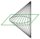 Actually the previous one should be called a mono-oblique duospindle. There is also a bi-oblique duospindle: the planes containing the two circles are absolutely perpendicular, so they intersect at a point, and the center of each circle can be offset within its own plane away from this intersection point. If both are offset by one radius, one obtains a bi-oblique duospindle that likewise cannot roll continuously. This critical-position bi-oblique duospindle is the convex hull of two absolutely perpendicular circles intersecting at a point, and no longer has any rotational symmetry.

Switching between multiple rolling modes
There is also a large class of objects that can switch between multiple rolling modes; they are all intersections of several different surfaces. They can be divided into smooth switching and flip switching. Smooth switching requires that several surfaces share the same tangent plane and intersect at special points, such as the various crinds containing special points; flip switching is ordinary intersection, such as the duocylinder obtained by intersecting two absolutely perpendicular cubinder surfaces, and the previously seen duocylindrical frustum, which combines cylinder and cone rolling directions and can switch rolling direction after flipping 90 degrees. For example, if one wants a stable switch between cylinder and conic modes through a special point, one should find the intersection of some cylinder and some cone, and ensure that at an intersection point there is a common tangent plane. This corresponds to the shape of the plaster cast combination models art students often draw; this figure is obviously no longer symmetric, and the changing center of rotation causes discontinuous rolling. 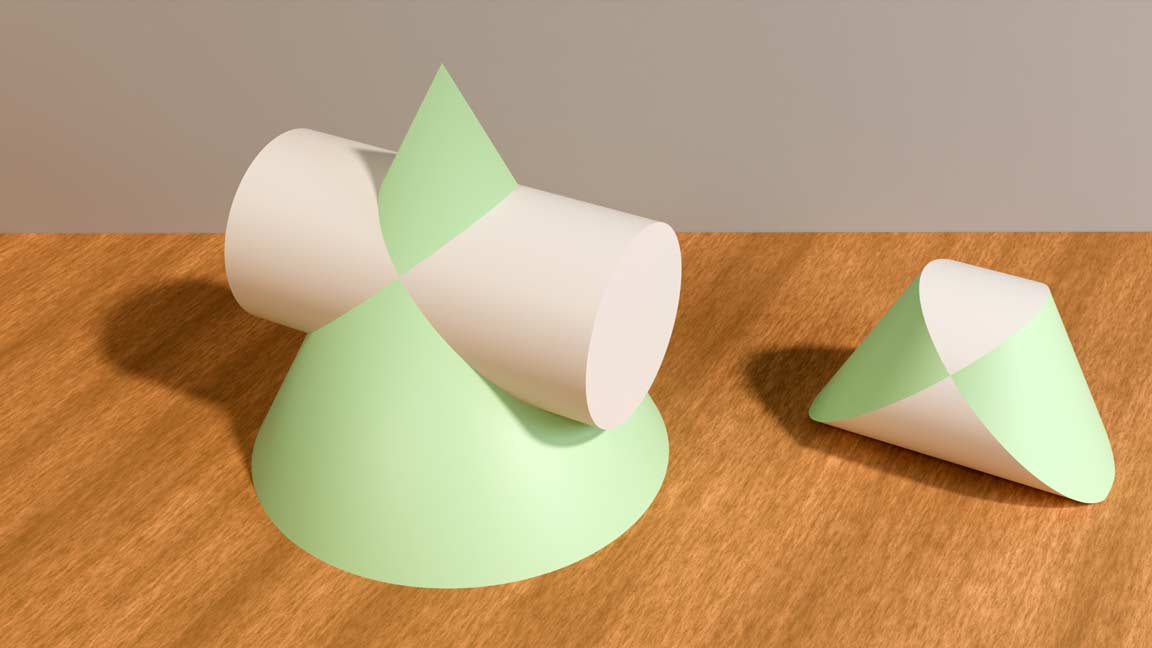 Finally there are unstable special points: they are not coincident 3D tangent cells of the intersecting shapes themselves, but coincident intersection lines or intersection faces produced by the intersection. The cone point of the duocylindrical cone we saw earlier belongs to this case.
A Puzzle
Here is a somewhat challenging puzzle / exercise for readers: take the intersection of three equal duospindles centered at the origin, with orientations respectively xy/zw, xz/yw, and xw/yz. What does this shape look like? Are there tangent special points on this shape? What is the set of projections of the object’s center of gravity onto the contact surface when it rolls? Hint: think about how the 3D object below comes about. 