Play Tesserxel (III): Train and Flight Simulator
This article will introduce the operation tutorial for four example scenes in Tesserxel: the 4D linear track train (traditional railway + train), the planar track train (also called planar train), the drone, and the 4D aircraft. The scenes introduced in previous articles were static; we only actively operated the camera to observe the scenes themselves or 3D photos from different 4D and 3D angles. This article focuses on how to drive and operate these 4D vehicles, especially how to control the takeoff and landing of the 4D aircraft. The design details and operating principles of the vehicles corresponding to these scenes have already been introduced in previous articles. If you are interested, you can check them out:
- Linear track train and planar track train: 《4D World (III): Road and Track Design》
- 4D drone and 4D aircraft: 《4D World (IX): Aircraft Design》
Tip: If you find the example scene sidebar on the left to be a hindrance while playing, you can click on the ‘hide sidebar’ button at the top and set the browser to full-screen mode for the best experience.
Linear Track Train Scene
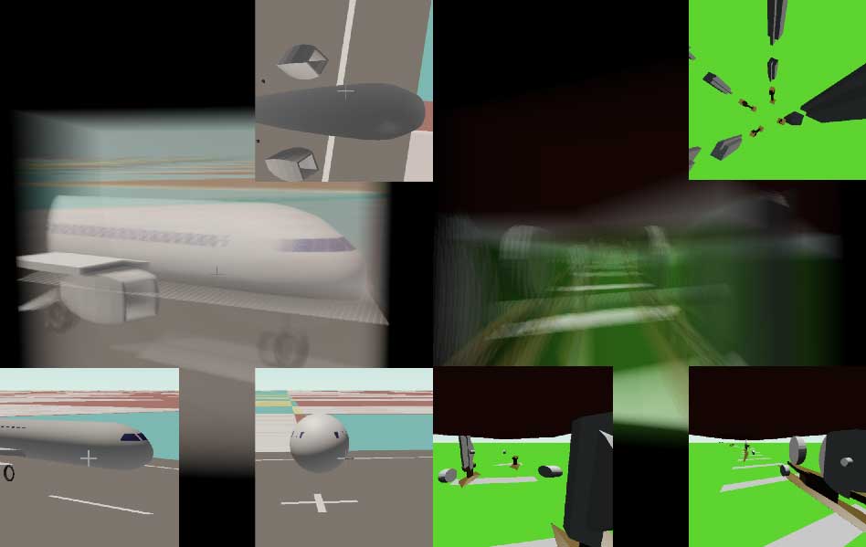
Click on 4D Scenes -> Linear Track Train in the sidebar. After the scene loads, we see a section of 4D railway with a train of three flatbed cars parked on it. Tip: If you can’t see stereoscopic 3D without glasses, you can press Alt+Z or turn it off in the settings to avoid being bothered by the two views. The initial camera position is between the bottom of the train and the railway ground. If you hold down the Alt key and drag with the left mouse button (remember to press Alt+R to reset), you can see that the view is a railway with four tracks, consisting of rails and sleepers. Press the T/G keys to control the train to move forward and backward. The control method for the linear train is relatively simple; it can only go forward/backward, and when it reaches the end of the track, it will be bounced back. Look at the horizontal cross-section in the top-right corner; it cuts through the train’s wheels. As mentioned before, this view omits the gravity direction, allowing us to see the “full picture” of the 3D ground. It is recommended to click the gear button on the right and select a larger cross-section view (you can also press Alt+2) or magnify the horizontal cross-section view separately (you can also press Alt+6) in the order shown in the figure below to observe better. 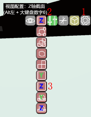 Pressing the Space or Shift keys to adjust the height up or down will cause the horizontal cross-section view to cut through different things, and the objects in view will continuously change. The images below show scenes where the cross-section cuts through the tracks or the carriages. This is very similar to the example of the 4D city highway scene in the previous article on playing Tesserxel. You need to be careful to look straight ahead; if you accidentally touch the scroll wheel, you need to re-adjust the camera’s pitch angle in the way described in the previous article.
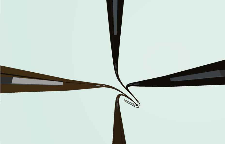
By moving the camera outside the track with the mouse (or Q/E/A/D keys) and looking at the train, you can find that the train has three carriages, each with a front and rear bogie. Each bogie has 8 wheels, just like a standard 4D car, so the train has a total of 48 wheels. For the specific design of the railway and wheels, please refer to 《4D World (III): Road and Track Design》.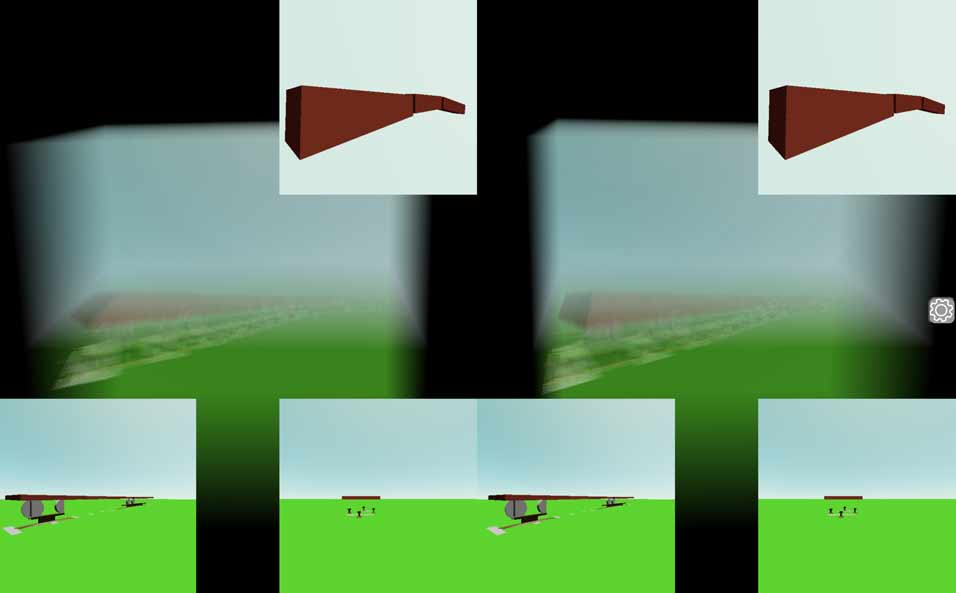
Planar Track Train Scene
Now let’s look at the planar track train scene. Click on 4D Scenes -> Planar Track Train in the sidebar. A planar track train is a fascinating object somewhere between a 3D world car and a train. The introduction to this can be found in this old article. When you open the planar track scene, at first glance, it doesn’t look much different from the linear track train. But when you hold down the Alt key and drag the mouse to rotate the 3D voxel photo (remember to press Alt+R to reset!), you can see that this planar railway is almost the result of up-dimensioning a normal 3D railway by extrusion in one direction, thus forming two parallel planar tracks. 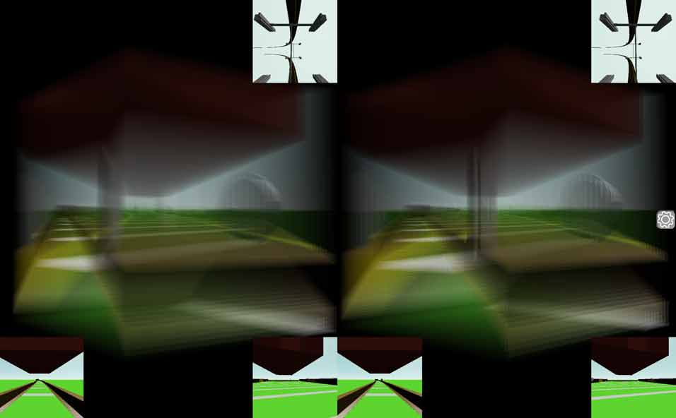 The “planar train” that runs on this track can not only be controlled to go forward and backward with the T/G keys like the linear train, but also be steered with the R/Y keys to turn the front wheels. When the train starts moving, you will find that although the camera in this scene can move freely, it will default to following the planar train. You can press the B key to toggle between following and not following. Currently, there is a bug where the camera’s pitch angle cannot be changed in follow mode. If you want to look up or down, please press the B key first to turn off the automatic follow mode. When the train is stationary, pressing the R/Y keys will allow you to see the front wheels turning in the horizontal cross-section view. Note that this steering has only one degree of freedom, not three like a 4D car (don’t forget 4D cars have self-rotation). Be aware that if the train hits the guardrail, a window will pop up saying the train has derailed, and you must refresh the page to continue playing. For details on what causes derailment, see the description of the lanes below.
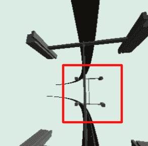
Before I talk about how to drive the planar train forward, I want to discuss the details of the train’s wheel steering system, which were not covered in previous articles. When I started creating this planar track train simulation scene, I realized it couldn’t just have front-wheel steering like a car with fixed rear wheels. Because the planar train’s rear wheels are on the track, it might experience spatial curvature as shown in the figure below, so it also needs a bogie with only one degree of freedom. This bogie can only rotate along the red arrow. Similarly, the front wheels also need a bogie, but their wheels can swing along the green direction controlled by the steering wheel, just like a car’s front wheels. It can be said that this thing has both the car’s and the train’s steering systems from the 3D world, with each managing movement in one direction. 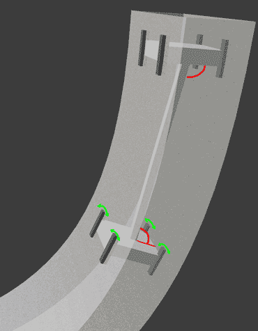
If the planar train is in its default position after loading the scene, pressing the T key to move forward now will allow it to follow the tracks in a slow left turn without steering at all. This turn corresponds to the red direction of the bogie in the figure above. After the left turn, it will come to a turn in the ana/kata direction, and this turn requires operating the planar train like steering a car. If you don’t use R/Y to control the direction at this point, the planar train will rush out of the curve, hit the guardrail, and derail. It is important to note that the two strips seen in the horizontal cross-section view are not the tracks, but guardrails on the side of the road to prevent derailment. We can see these guardrails in a vertical or side cross-section view, such as the cross-section in the bottom right corner of the figure below.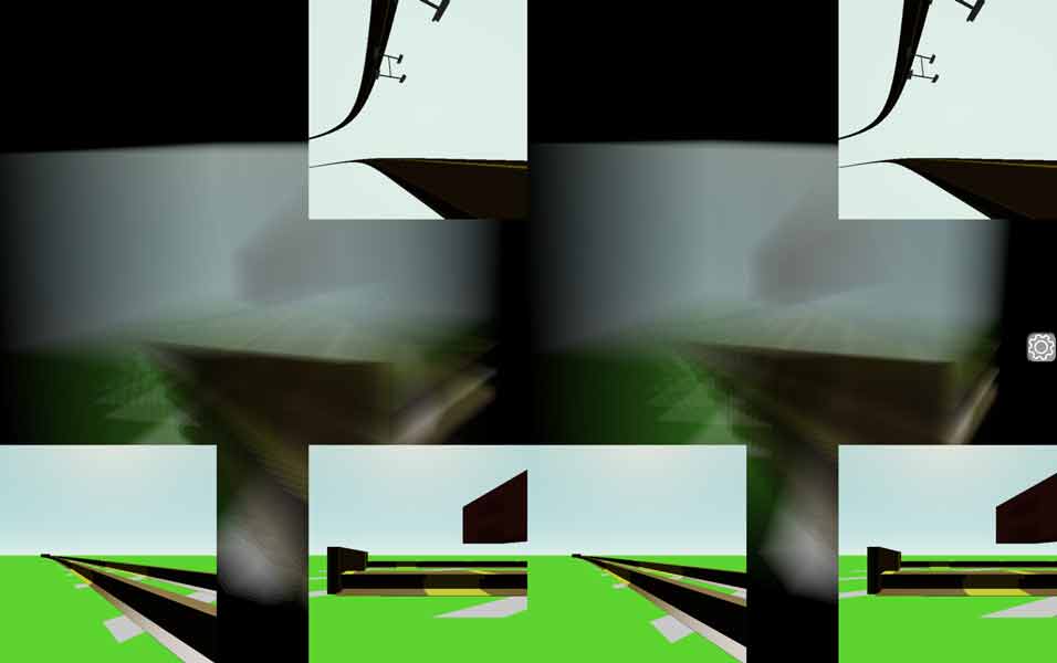
Because the planar track can be steered like a car, this railway is actually painted with lane lines, just like a highway. You can raise the camera by pressing the Space key and then scroll the mouse wheel to look down at the tracks (if you cannot change the camera’s pitch angle, press B to turn off camera follow). For example, the image below clearly shows that the tracks are divided into 5 lanes by yellow lines. From the horizontal cross-section in the top-right corner of the figure below, you can also see that the guardrails at both ends of this railway are actually very similar to the bumpers at the end of a 3D world railway.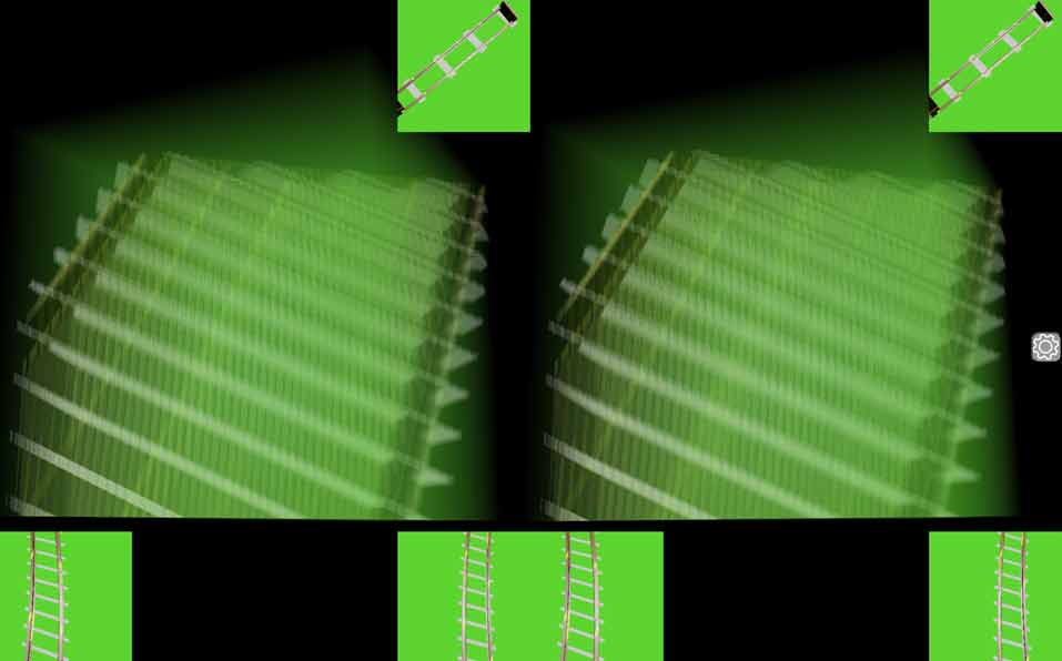
4D Drone
Click on Physics World -> Drone in the sidebar. After the scene loads, the drone is stationary and is in drone control mode. Now let’s look at the tutorial for operating the 4D drone.
Drone Takeoff
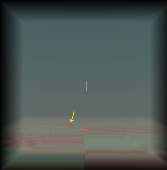
You can now press the Space key a few times, and the drone’s propellers will spin up and take off. If you hold down the Space key, the drone will fly out of the camera’s field of view. You can try quickly and briefly pressing the Space key to try to make the drone hover in view. Pay close attention to the height parameter highlighted in the figure, which indicates the drone’s height relative to the ground.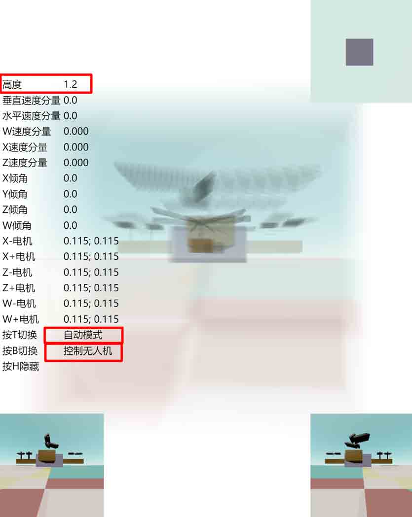 Here’s how to switch between automatic and manual modes: After pressing the T key to switch to automatic mode, the Space key makes the drone ascend, and the Shift key makes it descend. If you don’t press any keys, the drone will automatically adjust the propeller speed to achieve a slow hover. Due to flaws in the automatic control system, the hovering stabilization process is a bit slow and can have some drift. You can alternate between the Space and Shift keys to eventually get the drone to hover at a suitable height.
Switching Views to Observe the Drone
Press the B key to toggle whether the keyboard controls the drone or the camera. When switched to camera mode, the Space/Shift keys will control the camera’s up/down movement, and you will no longer have control over the drone. When switched to drone mode, all keyboard operations are for the drone, and you cannot move the camera, but since mouse operations are not used to control the drone, you can still drag the mouse to turn the camera. The camera does not follow the drone’s movement by default. To switch to a camera position that follows the drone, just press the number keys 1, 2, or 3. Note that pressing Alt + a number key switches between different view configurations for rendering voxel photos and other modes, and is no longer for camera position selection. When you select these camera positions that follow the drone, the camera is bound to the drone, so you cannot directly control the camera. The system will therefore default to drone control mode.
Manual Mode Practice for Level Flight
After the drone takes off, we definitely want to be able to control it to fly horizontally. The experience of flying horizontally in manual and automatic modes is quite different. To understand the flight control principles, let’s first try manual mode. Press 1 to switch to the view that follows the drone. Hold down the Space key until the drone rises to an altitude greater than 200 meters. Pay attention to the vertical velocity component to judge the drone’s ascent speed. It’s a good idea to fly a bit higher first to have enough altitude for potential “dangers” that might arise later, to prevent the drone from crashing to the ground immediately. Lightly press the D key, and you will find that the drone begins to tilt to the right (reflected by the horizon in the bottom-left cross-section tilting to the left). When the tilt reaches a certain angle (preferably not greater than 30 degrees), press the opposite A key to brake the tendency for the tilt angle to increase. Remember to press the Space key a few times to maintain altitude to prevent a crash. When the tilt angle is stable, hold down the Space key to give the drone power. The tilted drone will then generate an acceleration component to the right and begin to accelerate for horizontal flight to the right. To decelerate the drone, you need to press the A key to tilt the drone to the left, then decelerate. When the speed is almost 0, you must also adjust the drone back to a horizontal attitude, otherwise the drone will change from decelerating to the right to accelerating to the left. To control forward/backward movement, use the W/S keys. The operation is the same as for left/right movement. Similarly, there is movement in the ana/kata directions controlled by the Q/E keys.
I found a feature in the simulation, which is that pressing the W/A/S/D/Q/E keys to adjust the drone’s tilt angle while holding down the Space key works faster than when the Space key is not pressed. This provides coarse adjustment and fine adjustment functions. When you need to fine-tune the drone’s angle, it is recommended to hold down the Space key while adjusting. Conversely, when the drone’s tilt speed is too great and needs to be corrected in time, it is recommended not to press Space/Shift and to directly use W/A/S/D/Q/E to control the tilt angle.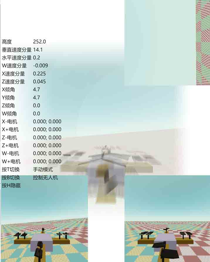
In addition to translation, there are also rotation controls that do not involve gravity on the 3D ground. These are simpler than translation: directly use I/J/K/L/U/O to control rotation, with no risk of the drone flipping over. If the drone is out of control and keeps rolling, pressing T to immediately enter automatic mode still has a good chance of recovering and saving the drone.
Automatic Mode Practice for Level Flight
In automatic mode, the drone will never roll upside down, and translation will be easier to control. The keys are the same, so you can experience it yourself. Finally, if you want to turn off the drone’s propellers and stop them from spinning, you must switch back to manual mode, whether on the ground or in the air, because in automatic mode, the drone’s algorithm continuously controls the propeller rotation to approach the target speed, and the blades will keep spinning even when it’s on the ground.
Identifying the Rotation Direction of Drone Propellers
Let’s use this scene to look at the structure of the drone’s propellers and how to identify their rotation direction. Although the previous content did not require readers to have read 《4D World (IX): Aircraft Design》, this section requires the content from the drone design as a foundation. If you are not interested, you can skip this section.
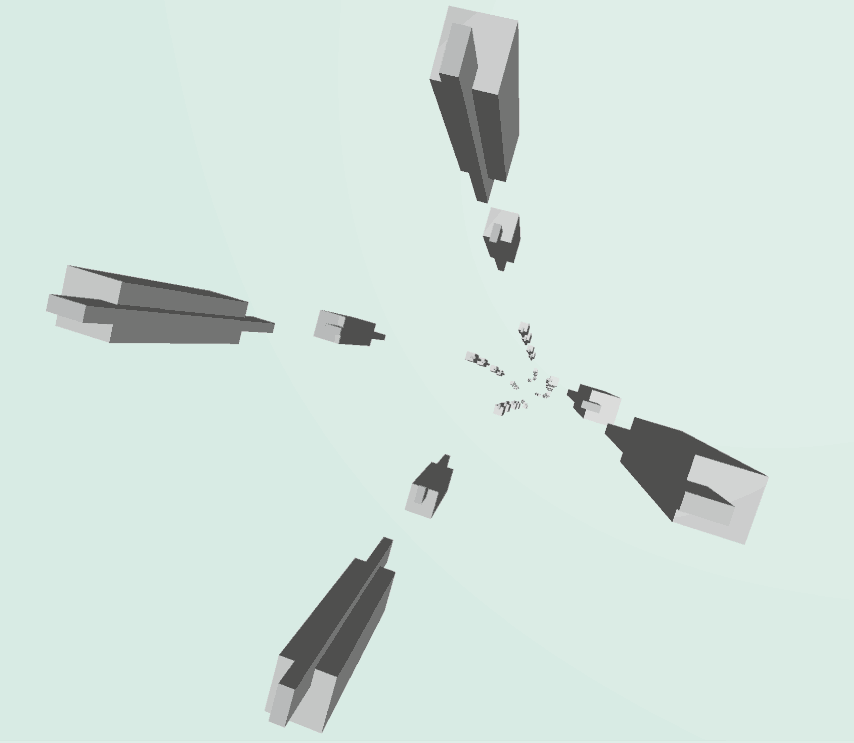
First, we press the number pad key 2 to switch to a camera position on the drone, where the horizontal cross-section happens to cut through all the propeller blades, making it easy to see their rotation direction. Since the horizontal cross-section does not contain the gravity direction, we cannot see the tilt direction of the blades from it, nor can we judge whether the current rotation direction will cause the blades to generate lift or downforce. We need to find this in other views.
If you have stereoscopic 3D display enabled, press Alt+Z to turn it off, as the parallax between the left and right eyes might be a bit distracting later. First, let the drone stay on the ground and switch to manual control mode. Press 1 or 2 to align the camera with the drone, then press B to switch back to camera control mode. To observe the left propeller, you need to press the A key to slowly pan the camera to the left, moving the propeller you want to observe to the center of the screen. At this point, a complete 3D blade shape will appear in the bottom-right cross-section. Now, press B to switch to drone control mode, lightly press the Space key once, and you can see the complete rotation of this blade. From the tilt direction, you can see that its rotation direction does indeed generate lift. Similarly, the propellers in the ana/kata directions can be seen using a similar method, but you need to use Q/E to move them to the center of the screen, and the complete propeller will appear in the bottom-left cross-section. (Tip: You can press the shortcut Alt+C to enable the crosshairs to help locate the center of the screen).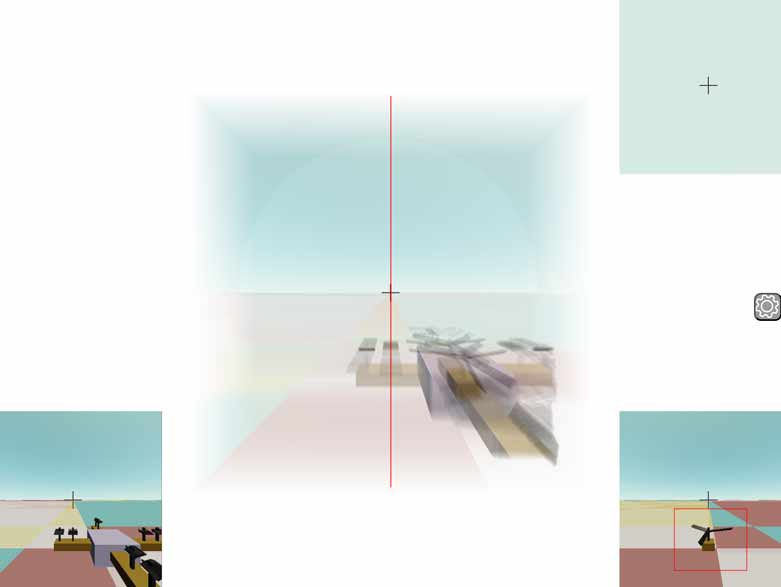 How can we see the rotation direction of the front and rear propellers? Unfortunately, no cross-section can perfectly show its direction. Is there no way? Actually, we can directly see the vertical tilt direction of the front propeller in the 3D voxel view. The front propeller is the closest to the camera. In camera control mode, press the W key to move forward, and you can see a propeller on a horizontal plane in the screen getting bigger and bigger; that’s the front propeller. It’s recommended here to directly press Alt+3 to turn off all cross-section displays and just press Alt + left mouse button to drag and view (it is recommended to enable stereoscopic 3D here if you can see it, the shortcut is Alt+Z). As for the rear propeller, the occlusion is too severe; to see its rotation direction, you can only go around to the back. In fact, the front/rear, left/right, and ana/kata propellers are symmetrical. You can also adjust the camera to face the left/right propellers, and then you can use the same method to view the front/rear propellers. After adjusting the camera position, press B to switch to drone control mode. In manual mode, a quick press of the Space key will show that the front propeller’s rotation direction also generates lift.
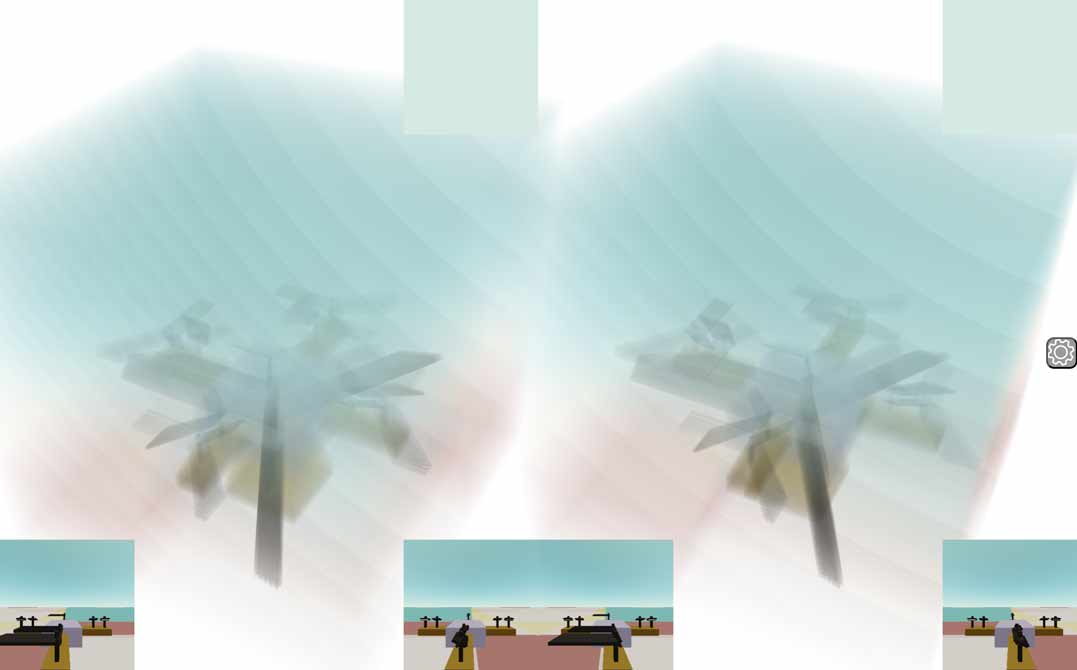
4D Aircraft
Now let’s look at the grand finale of this article, the 4D aircraft flight simulator. Click on Physics World -> Aircraft in the sidebar. I remember playing with Google Earth in elementary school and being pleasantly surprised to find that it came with its own flight simulator. Although it looks a bit rudimentary now, I never got tired of playing it back then.
As we know, the 4D ground is 3D, and driving on a 4D road has the same degrees of freedom as flying in 3D air. However, a 4D plane can add another altitude direction on top of this. What would the experience of a 4D flight simulator be like? Unfortunately, I haven’t found any 4D flight simulators on the market, so I had to use Tesserxel’s physics engine to hand-craft one.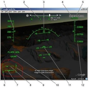
4D Aircraft Structure
Open the aircraft scene under Physics World, and after the scene loads, you will see an aircraft parked on the runway. The default mode is camera control mode, and you can first walk around the plane to observe its structure. If you are not interested in the plane model’s structure and just want to experience flying it, please press the digit key 1 to board the plane, which will automatically enter plane control mode. For specific operations, please see the next section.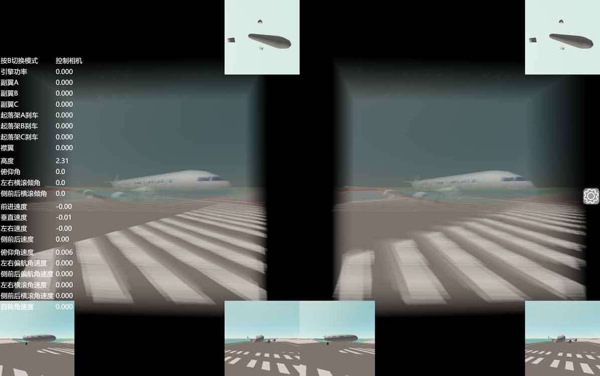
Since the 4D plane model has many parts and is too complex, let’s first get to know the specific parts from the cross-sections, and then try to identify them in the voxel view. First, let’s review the operations for moving around on the 3D ground: focus on the horizontal cross-section in the top-right corner. You can choose a large cross-section mode (Alt+2) or a mode that only shows the horizontal cross-section (Alt+7), according to your personal preference. Dragging with the left mouse button can change the direction on the 3D ground, W/S for moving forward/backward, A/D for moving left/right, and Q/E for moving up/down. Note that this is “up/down” as it appears in the 3D ground view. The horizontal cross-section actually omits the true up/down gravity direction, and the movement corresponding to the Q/E direction is actually the ana/kata direction. The real movement in the gravity direction is controlled by the Space and Shift keys. By adjusting to different altitudes, the horizontal cross-section will cut through different things. For example, we can see the distribution of windows on the plane, the three wings distributed symmetrically at 120 degrees. From the position where the cross-section cuts the wings, we can see that the wingtips are slightly upturned. We can also see the horizontal and vertical stabilizers of the tail and the wheels of the landing gear at the very bottom. Why these things are constructed this way is not the subject of this article; for the specific design principles, please refer to 《4D World (IX): Aircraft Design》.
Some readers may not be used to viewing the horizontal cross-section, which lacks the gravity direction. The vertical cross-sections often look a bit strange because they don’t cut through the plane’s important structures. For example, because the wings and landing gear wheels are distributed at 120 degrees, after aligning with the plane by pressing 1 and then pressing B to regain camera control, you can see that everything on the plane in the bottom-left cross-section is only a half. To see the other hidden parts, you can press the Z/X keys to rotate the camera’s self-rotation, which in turn rotates the cross-section.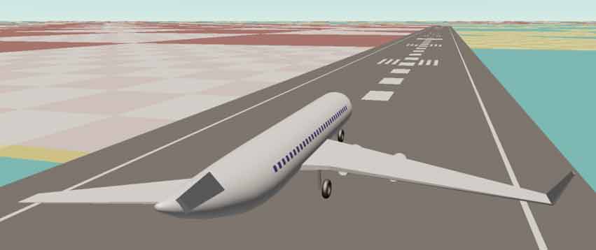
A way to see the full plane is to look down on it. We can press the Space key to ascend, and then use the mouse scroll wheel or K key to look down at the ground. After adjusting the angle appropriately, you can see the plane with 120-degree wings and tail. Don’t forget that the voxel view is 3D, so you can occasionally press the Alt key and drag it to rotate to understand the structure in the 3D view. Remember to press Alt+R to reset afterwards to avoid getting disoriented.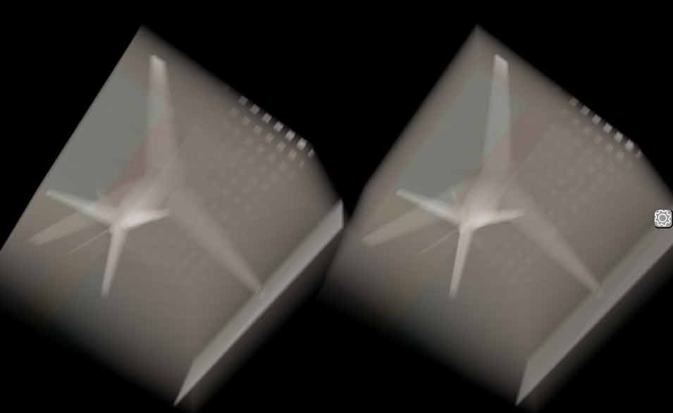
Knowledge about the Runway
You might have noticed some neat white square dots in the ana/kata direction in the previous top-down view of the 4D plane. These are actually the white lines painted on the 3D ground runway. Before explaining the 4D runway further, let’s first get familiar with our 3D world runways. This is an image I found online: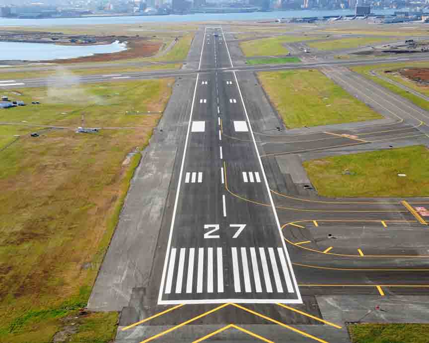 The “zebra crossing” lines at the end of the runway are for incoming planes to estimate the runway width. Further along, in addition to the white dashed center line, there are also some white bars, which are used to help pilots calculate the landing point. The best landing point is the area corresponding to the two large white blocks. I have up-dimensioned these things to 4D. The white dashed center line becomes a crosshair lofted dashed line. The crosshair takes up more voxel space in the 3D field of view than a simple 3D line and is easier to be cut by a cross-section for us to observe.
The landing markers become a circle, like a bullseye pattern, making it easier for 4D pilots to aim. The cross-section of the 4D airport runway here is square, mainly because it is easy to model, but I think a circular shape might be better, or perhaps even a triangular shape corresponding to the plane’s wings to further reduce the land area occupied by the runway. 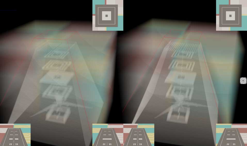
4D Aircraft Takeoff
Press the number pad key 1 to switch to the camera view on the plane. Similar to the drone, the system will automatically switch to plane control mode. If you want to switch back to camera control, press the B key. Now, press the up arrow key to open the throttle (increase engine power), and the plane will slowly taxi. Use the W/S keys to control the elevator. When the plane’s speed reading exceeds 70, press the S key a few times in quick succession to pull up, and the takeoff is successful. After takeoff, you need to use the W/S keys to keep the plane’s pitch angle within a certain range, around 15 degrees is recommended, and it should not exceed 30 degrees. If you pull up the plane forcefully with insufficient speed, either there won’t be enough lift, or the plane’s nose will pitch up but the tail will hit the ground, causing it to scrape and bounce. A well-designed plane shouldn’t do this, but I couldn’t debug it better with my current abilities. As long as you follow the correct procedures, takeoff should be fine.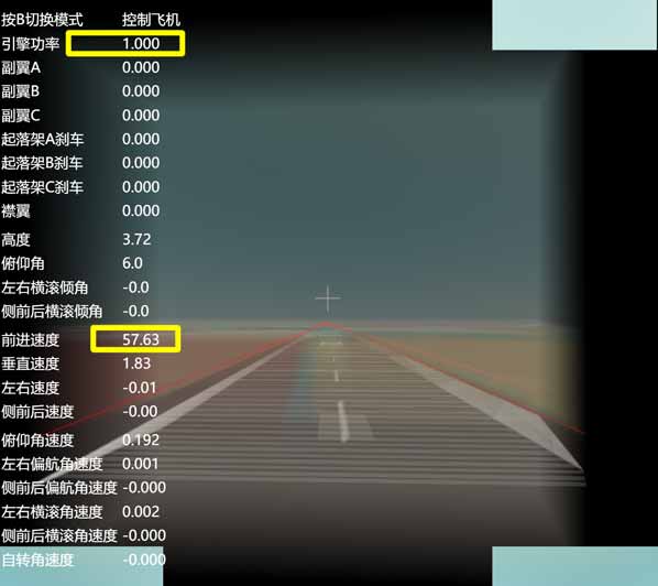
Beginner’s Landing Practice
In fact, the flight simulator does not have a system to determine whether a plane has landed within the runway. If you don’t want to practice landing, you can completely ignore the runway and land anywhere. But to successfully land on the runway still requires some practice. If the takeoff process went smoothly without any ground contact or bouncing, the plane will be aligned with the other runway in the distance. We will practice landing there. If you find the plane is skewed after taking off, you can refresh the page to start over. This is likely caused by pulling up too early or too forcefully during takeoff. Or, you can refer to the novice landing practice section below to adjust the plane’s attitude. Since the direction is already aligned, all the following operations only control the plane’s pitch angle, horizontal speed, and vertical speed. The edges of the runway are highlighted with red boxes in the voxel view, so you don’t need to observe the runway in the cross-sections.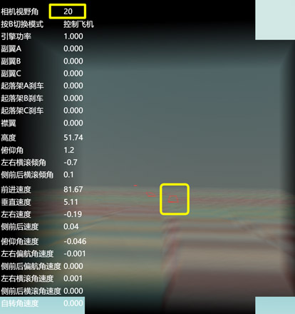
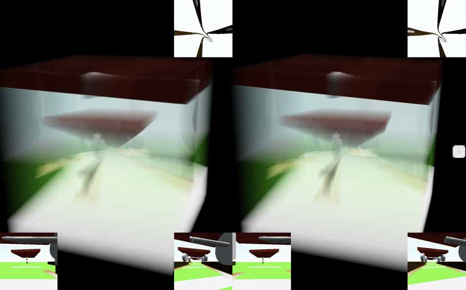
When the runway is far away, you can press the number pad keys 9/0 to zoom in/out the camera to see the distant runway clearly. Be careful to zoom back out later, as it will be inconvenient for observing the landing. You can refer to the camera field of view parameter in the yellow box in the figure below; the normal value is around 90.
By holding down the Alt key and dragging the mouse, you can find that the runway you are facing is a frustum. After observing it, remember to press Alt+R promptly to restore the voxel view to facilitate observation during landing.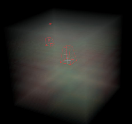
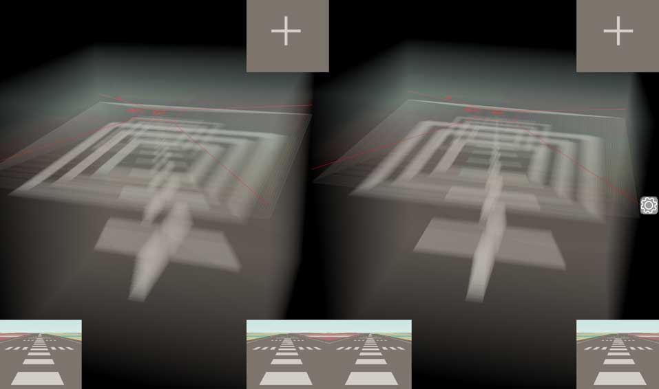
Now for the specific landing procedure. Since the landing runway is actually very close to the takeoff runway, it is recommended to adjust the plane’s pitch angle to maintain level flight after climbing to an altitude of around 80. Do not exceed 150 in altitude during the flight. When you see the runway becoming very long as shown in the figure below, it means you are flying too high and need to start descending and immediately prepare for landing.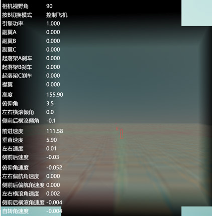
When preparing to land, you should also press the down arrow key to adjust the throttle to around 0.5. Do not fly with full throttle to avoid being too fast and overshooting the landing, and do not cut the throttle too early, otherwise the plane will lose speed and lift, causing it to crash. It is recommended to maintain a horizontal speed of at least 60 to avoid stalling and crashing. After aligning with the runway, press the F key to extend the flaps (Shift+F to retract them). Flaps help the plane decelerate and provide lift. Press K to engage the landing gear braking system. When the plane is about to touch down, you can completely cut the throttle. When the plane touches the ground, if the angle is too large, it will bounce up. You can press W to push the nose down as needed. If it bounces too high, you need to re-adjust the plane’s pitch angle and should not blindly push the nose down, which would result in too large a landing angle and cause the plane to bounce again on the next touchdown. If the plane deviates from the runway during taxiing after landing, you can use short presses of J/L to adjust the brake balance of the various wheels to make the plane turn left or right. Use U/O to make the plane turn in the ana/kata direction. It is recommended to observe the plane’s left/right deviation in the bottom-left cross-section view and the ana/kata deviation in the bottom-right cross-section view.
Here is a summary of all the shortcut keys in plane control mode: Red is for direct key functions, blue is for view control functions that require holding down the Alt key, and green is for functions that require holding down the Shift key.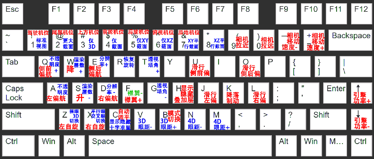
That’s the entire process for landing a plane. It’s likely that when you first start, you’ll overshoot the runway, have too steep a landing angle, land too fast and run off the runway, or land too slow and crash prematurely. After refreshing the browser and practicing a few times, this beginner-level runway is actually easy to handle, as we only need to control the plane’s state in the up/down and forward/backward directions, without extensively involving all four dimensions at once.
Novice’s Landing Practice
While playing the beginner’s landing practice runway, you should have noticed that there is another slightly skewed runway not far to the ana/kata direction of the starting point. This time we will try to land the plane on that runway. The difference from the beginner’s runway is that this time we must manually control the plane to align with the runway in the left/right direction before landing. Compared to the intermediate difficulty, this runway is only skewed in the left/right direction and does not require us to make large adjustments in the ana/kata direction, perhaps only fine-tuning.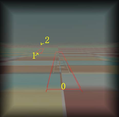
Here are the steps for operation. First, take off normally. When the plane is stable, press the number pad key 9 to zoom in and find the runway we want to land on. Press the A/D keys to adjust the plane’s rudder, and the plane will slowly begin to turn. This is very similar to playing a 3D flight simulator. When you are close to being aligned, remember to straighten the plane’s attitude. If the plane is banked to the left or right, you can hold down C until the plane’s automatic control system adjusts the plane’s attitude to horizontal, then release it. When the runway shape changes from a general trapezoid to an isosceles trapezoid and is centered on the crosshairs, it means you have aligned with the runway. The rest of the landing process is the same as the beginner’s level. The only difference is that the plane’s direction might have a larger deviation from the runway’s direction, so you must use J/L/U/O to control the brake balance of each wheel to prevent skidding off the runway.
Here are some more tips:
- The red box on the outside of the runway is just to help us see the runway clearly in the stacked voxels, and its length is a bit longer than the actual runway. The gray pavement is the runway itself. Be careful not to land too early outside the runway or run off the runway.
- When the target runway still looks like an obtuse trapezoid, don’t rush to turn, because this means the plane’s current position is still far from the line on which the runway’s axis lies. It is recommended to wait until it becomes a right angle before turning. After you finish the turn, it should become an isosceles trapezoid.
Intermediate Landing Practice
Finally, let’s challenge a very difficult landing runway, which is also the furthest from the takeoff runway in this scene. This runway is skewed in both the left/right and ana/kata directions. In theory, if you learn to land on this runway, you will have the ability to fly a 4D plane to any airport and land. First, take off normally, and press the number pad key 9/0 to find the runway to land on. Like the previous runway, don’t rush to turn. This runway is even further away, so fly for a while until you see the obtuse angle of the runway’s trapezoid slowly straighten before turning.
After quickly aligning the left/right direction so the runway frame looks like an isosceles trapezoid, we press Alt + L (or hold down the Alt key and drag the voxel view to the left), observing from the right side of the voxel origin. You can see that the ana/kata direction is not aligned at all. Use Q/E to adjust it continuously, just like adjusting the left/right direction, until the ana/kata view also becomes an isosceles trapezoid. Then press the Alt+R key to return to the left/right view. If the left/right direction has deviated again, you need to continue adjusting. You can also press Alt + I (or hold down the Alt key and drag the mouse) to look down at the voxel view, so you can see deviations in both the left/right and ana/kata directions at the same time. The runway boundary lines now look more like a long strip floating in space, and the plane needs to dock with it like a spaceship. You can switch between these views according to your personal habits, observing and adjusting. Once you have confirmed that all directions are aligned, you can approach the runway and land.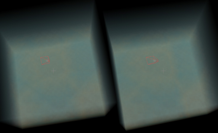
The operating principle has been explained, but in practice, the difficulty is still quite high. My current success rate for landing on this runway is less than half… Here are some suggestions:
- Throughout the process of aligning with the runway, you only need to look at the voxel view. The cross-section views are almost useless, because unless the runway happens to pass through some intermediate slices of the voxel, or is already perfectly centered and aligned, it will not appear in the cross-section view at all.
- Don’t focus solely on aligning with the runway. You must constantly pay attention to your altitude, speed, and pitch angle. I often find that after finally aligning with the runway, the plane’s speed has dropped to 30 or even lower, resulting in an immediate stall and crash.
- If you make continuous turns, the plane’s left/right (labeled X) and ana/kata (labeled Y) bank angles will become too large. Don’t forget to hold down C to correct the plane’s attitude in time, especially during landing, when you should try to keep the plane as level as possible.
- If you accidentally fly past the runway, it is recommended to just refresh and start over. The turning in this flight simulator I wrote is not very flexible, and the turning radius is huge. Turning back is often more difficult than finding the runway to land on. Of course, you can challenge yourself if you want to.
- During the initial turns after takeoff, it is not recommended to drag the voxel view frequently. It is better to align one direction first, and then the other. Later on, do not focus on being excessively precise in one direction; you must balance both sides, especially when you are about to land. After all, as long as you land on the runway, there is still room for adjustment during the taxiing.
Finally, I want to say that while operating this 4D aircraft may be a bit difficult, it’s not so terrifying for a 4D person, for two reasons. The first is that this flight simulator was hand-crafted by me, a person with no experience in aircraft design. The various physical model parameters are not very reasonable, and the operation is indeed a bit clunky. I continuously test-flew and adjusted the parameters for more than a week to get the plane to its current state, which is only “flyable.” For example: The plane’s body is a rigid body model in the physics engine. To simulate the elasticity of the landing gear upon touchdown, the wheels are tied to the rigid body with a hard spring model. When airborne, the rigid body flies while being suspended by the springs from the wheels. If the wheels’ positions are not suitable, it will cause the plane’s center of gravity to be too far forward or backward, leading to the nose sinking or pitching up. In addition, there are a large number of parameters to adjust, such as the aerodynamic center position of the control surfaces, and the lift and drag in various directions for each component. So it’s not that I didn’t want to make it better, but I was truly overwhelmed.
The second reason why operating a 4D plane is not that difficult is that a 4D person’s eyes naturally see the voxel view. They don’t need to struggle with dragging the mouse around like we do to align with the runway. Therefore, just like 3D planes, 4D planes are still a very safe, stable, and popular means of long-distance transportation for most of the time. Of course, 4D fighter pilots and stunt pilots are indeed highly respectable and difficult professions.
Answers to the Previous Article’s Question
In the previous article 《4D World (IX): Aircraft Design》, the top and front views of the 4D plane were shown, but the other two side views from the four-view drawing were not. Here are the answers. 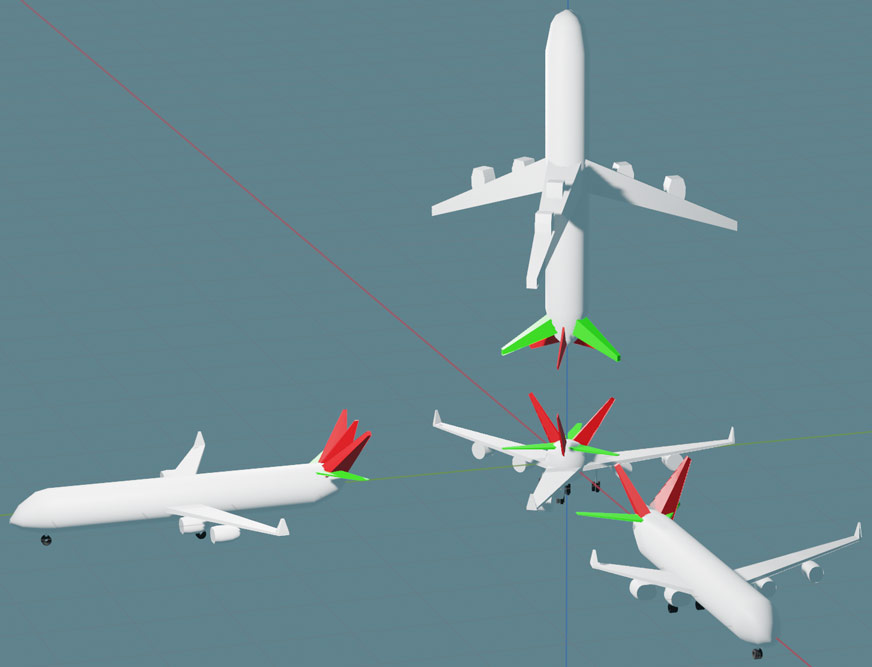
You can see that the side view looks most like a 3D plane, but there are still some differences. I will list some of the most obvious ones: First, the structure and number of tailwings are different. Second, in one view, the two wings on the sides are of different lengths (their lengths differ by exactly half—think about why). Third, the engine area is solid because the engine intake is facing forward, so you can’t see into it from the side.
Finally, here is a wireframe animated version, which shows that the three views of the four-view drawing are the same in their corresponding directions: