4D World (VI): Newtonian Mechanics
This series has been imagining a fictional four-dimensional world. No matter how we describe its appearance in words, a world lacking physics is static and non-interactive. So today we’ll study Newtonian mechanics in this world. The construction philosophy of this world is to be as close as possible to our real world, differing only in dimensions, so we can simply copy all the theories from the 3D world. Following 3D game physics engines, we can also write a 4D physics engine. For example, Marc ten Bosch’s 4D Toys is quite good, but the game only allows fixed movement of cross-sections (2024 update: it seems the author later added rotation functionality), and you can’t customize scenes, so I reinvented the wheel and wrote my own.
Preview
If you don’t know what 3D vision is yet, please read the tutorials first and come back:
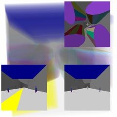
Here are many 4D physics scenes (more may be added in the future), where you can freely rotate the viewing angle. Unfortunately, besides being able to right-click to fire hypersphere cannonballs, I haven’t thought of better ways to interact with objects. (It’s best to read the explanations below for a better experience)
4D Car
Operation Method
Use W S for forward/backward, J L I K for left/right and lateral forward/backward steering, U O for rotation. The camera is fixed to the car, press number keys 1 2 3 to switch between three viewpoints.
Explanation
This is a hyper-rectangular rear-wheel drive car with 8 duocylinder wheels. The physics engine directly applies torque to the four rear wheels, and applies torque to the front wheels when turning. The car moves forward or steers naturally through friction calculated by the physics engine. This 4D car is mainly to verify the concept of 4D vehicles in the article “Four-Dimensional World (Part 2): Road Traffic”. It’s recommended to read together with that article.
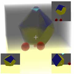
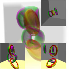
4D Gyroscopes
We mentioned the rolling of different objects in the article “Four-Dimensional Space (Part 8): Visiting the Four-Dimensional Country”. Now let’s look at the rolling of various spheres, cylinders, and cones, whether cones can be used as tops when inverted, and their stability. We won’t prove this mathematically here, but will draw qualitative conclusions directly through experiments (or playing with toys). Switch between different scenes using the control panel on the right. You can right-click to fire hyperspheres to interact with objects. (Note that firing too many will slow down the scene calculation, and in severe cases will reduce calculation precision leading to clipping. The physics engine is too difficult to optimize…)
Rolling
Here are common 4D objects rolling on 3D ground: (Default degrees of freedom is 1 unless stated)
- Hypersphere: Can roll in any direction; (Degrees of freedom: 3)
- Spherinder: When laid flat, can move perpendicular to the generatrix direction (Degrees of freedom: 2)
- Cubinder and duocylinder: Both can only roll in one direction. The cubinder must be laid horizontally on the ground, but the duocylinder has circular bases and sides, so there’s no difference between horizontal and vertical - both can roll.
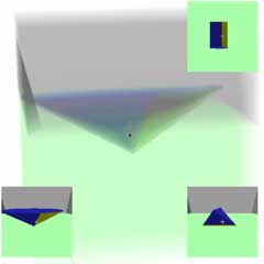
- Dicone: When laid horizontally on the ground (note that the base cell has an inclined angle with the ground, same below), the contact shape with the ground is a triangle, with two vertices being the two cone vertices and the other vertex being the tangent point of the upright circle with the ground. The dicone can rotate around the axis determined by the two cone vertices on 3D ground, just like a 3D cone rotates around its vertex when rolling.
- Coninder: Similar to the dicone. When laid horizontally, the contact shape with the ground is a rectangle, with one set of parallel sides in the cylinder’s generatrix direction, and the other set being the tangent lines between the cone base and the ground. It can rotate around the generatrix direction passing through the cone vertex as the axis, meaning the generatrix direction remains unchanged, feeling like the conic base is rolling in the 3D space perpendicular to the generatrix.
- Sphone: Tangent to the 3D ground along a line segment, with one end being the cone vertex and the other being the tangent point of the sphere cell with the ground. Can rotate freely around the cone vertex. (Degrees of freedom: 2)
- Duospindle (Duocone): Tangent to the 3D ground along a line segment. The two endpoints of the segment correspond to the tangent points of two absolutely perpendicular circles with the ground. The tangent lines of the two circles at the tangent points and the segment are mutually perpendicular. The duospindle can rotate around either endpoint with that endpoint’s circle tangent as the axis, while the other endpoint moves in the direction of that endpoint’s tangent. But the non-interference of absolutely perpendicular rotations allows the rotations at both ends to not interfere with each other, meaning there exists a double rolling where each endpoint moves in its own tangent direction. The duospindle’s rotation is the strangest and most difficult to understand, as we have no similar experience in 3D space.

Gyros
- Dicone: Place the two cone vertices on the ground and rotate in the plane of the circle. This gyro has stability: conservation of angular momentum ensures the rotation plane of the circle won’t tilt, while angular momentum is zero in the absolutely perpendicular rotation direction, but the two cone angles on the ground prevent rotation in this direction.
- Coninder: Place the cone line (generatrix passing through the cone angle) on the ground, with the cylinder cell flipped to be parallel to the ground, rotating in the plane of the circle. Equivalent to directly cylindrifying the entire 3D cone scene. Similar to the dicone, when rotating, the cone line on the ground prevents tumbling, also providing stability.
- Sphone: Cone point facing down on the ground, with the sphere cell flipped upward parallel to the ground. Rotation can be any simple rotation within the sphere cell (i.e., rotation parallel to the ground). But the sphone gyro has no stability, because there’s angular momentum in a direction parallel to the ground that maintains this plane from tilting, but the plane perpendicular to this plane can rotate, meaning the rotation axis within the sphere can rotate in the vertical direction. A small disturbance in this direction will make the gyro fall directly. Interestingly, even if the gyro falls, it won’t roll chaotically, because the angular momentum in the direction parallel to the ground will continue to maintain rotation stability. This means after falling, the gyro will continue rotating, contacting the ground along a line that connects the sphere’s rotation axis. All points on this line are stationary, so it won’t roll chaotically.
- Duospindle: Let one circle be parallel to the ground and the other perpendicular on the ground. Rotate in the plane of the circle parallel to the ground. Since the plane of the perpendicular circle has no angular momentum, any slight disturbance will cause this circle to fall, so there’s no stability. If it’s a double rotation, no fixed points can be found on the duospindle, and the vertical circle will act as a wheel causing the duospindle to roll away.
- Cylindrone: Like previous cones, there’s no stability in the direction perpendicular to rotation, and there’s only one cone point on the ground, unlike the coninder and cylindrone which have support, so it’s prone to tipping and unstable.
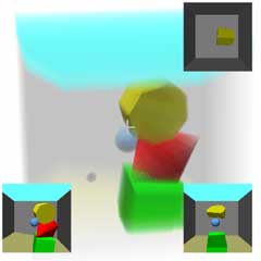
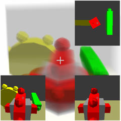
4D Gears
Operation Method
Expand the control panel on the right to adjust torque parameters to control the gear motor speed.
Explanation
4D Gear One is an absolutely perpendicular gear transmission mechanism. You can control the green gear’s speed to drive the absolutely perpendicular yellow gear. The principle of absolutely perpendicular gear transmission is achieved through two half-parallel half-perpendicular gear transmissions.
4D Gear Two is a double rotation synthesizer. The colored gear consists of two absolutely perpendicular single-disc gears connected together, which can be driven separately by gears in different perpendicular directions without interference.
4D Chains
Right-click to fire hyperspheres to interact with objects. (Don’t fire too many, it will crash…)
For details on how the specific geometric bodies are linked, please refer to this article: “4D Space (X): Knots and Links”.
Rigid Body Mechanics
The translational properties in 4D space aren’t much different from 3D, so we’ll mainly focus on rotation-related content here.
Representation of Rotation
Now let’s talk about the physics formulas behind this. The position vector of a point mass in 4D space is represented by four coordinates: $(x,y,z,w)$. Velocity is the derivative of coordinates with respect to time, also a 4D vector $(v_x,v_y,v_z,v_w)$. Acceleration is similar, so Newton’s three laws work fine in 4D. But for rigid body mechanics, besides calculating an object’s position, velocity, and acceleration, we also need to calculate the object’s orientation, angular velocity, and even angular acceleration. Rotation in 4D space is quite different from 3D. Representing an object’s orientation means representing a specific rotation. There are many ways to represent rotation, such as:
- $4\times 4$ orthogonal matrix
$$Ox=\left(\begin{matrix} a & b & c & d \\ e & f & g & h \\ i & j & k & l \\ m & n & o & p\end{matrix}\right)\left(\begin{matrix} x \\ y\\ z\\ w \end{matrix}\right)$$ - 4D analogue of Euler angles: Using compound rotations in fixed planes in a fixed order to represent arbitrary rotation. (May have issues like Gimbal Lock)
- Rotors in geometric algebra
$$RxR^\dagger$$
where $R = (a+be_{xy}+ce_{xz}+de_{xw}+ee_{yz}+fe_{yw}+ge_{xw}+he_{xyzw})$, $x=(xe_x+ye_y+ze_z+we_w)$, $R^\dagger=(a-be_{xy}-ce_{xz}-de_{xw}-ee_{yz}-fe_{yw}-ge_{xw}+he_{xyzw})$ - Quaternions
$$pxq=(a+bi+cj+dk)(x+yi+zj+wk)(e+fi+gj+hk)$$
The first two methods are easier to understand, but the computational complexity and precision for actual calculations may not be ideal, so the latter two methods are generally used. I won’t expand on the details here.
Angular Velocity
Then there’s angular velocity: What exactly is angular velocity? It reflects the direction and speed of rotation. In 4D, angular velocity is a 2-vector, as we mentioned before. Knowing the angular velocity $\omega$, we can determine the linear velocity at each point on the rigid body due to rotation:
$$v = r\cdot \omega = (r \wedge \omega^*)^*$$
Note that since $\omega$ now represents the rotation plane rather than the rotation axis, when generalizing from 3D to calculate linear velocity, we should originally use the cross product, but after the definition changes to the perpendicular direction, it becomes the dot product. For example: the unit angular velocity rotating in the zw plane is $e_{xy}$, the velocity at $e_x=(1,0,0,0)$ is $e_xe_{xy}=e_y=(0,1,0,0)$, while the velocity at $e_y=(0,1,0,0)$ is $e_ye_{xy}=e_ye_xe_y=-e_xe_ye_y=-e_x=(-1,0,0,0)$ (same letters multiply like dot product to get a scalar, different letters change sign when swapped, please refer to geometric algebra content for details)
Moment of Inertia Tensor
If you think rotation and angular velocity in 4D space are already hard enough to understand, then the moment of inertia is even more troublesome. We know that mass reflects how difficult it is for a force to change an object’s velocity:
$$F=ma=mdv/dt$$
The moment of inertia reflects how difficult it is for torque to change an object’s angular velocity:
$$M=Id\omega/dt$$
But moment of inertia is more complex than translational inertia - it depends on spatial orientation, and the direction of torque $M$ may not be consistent with the direction of angular velocity $\omega$, so generally the moment of inertia $I$ is a matrix. In 3D space, since $M,\omega$ only have three degrees of freedom $e_{xy},e_{yz},e_{zx}$ (equivalent to perpendicular vectors $e_z,e_x,e_y$), $I$ is a third-order matrix. Note that blindly extrapolating that $I$ is a third-order matrix in 3D to a fourth-order matrix in 4D is wrong, because $M,\omega$ in 4D are 2-vectors with six components, and the moment of inertia matrix $I$ is a sixth-order matrix! If you view 2-vectors as $4\times 4$ tensors, then the moment of inertia is a $4\times 4\times 4\times 4$ order tensor with many repeated components. Another example that shows direct analogy doesn’t work: the moment of inertia in 2D space only needs one number, not a second-order matrix.
Alright, these are the main differences in 4D Newtonian rigid body mechanics compared to 3D. With this theoretical foundation, we can write a physics engine.
How Does a Physics Engine Work?
Before planning to make a 4D physics engine, I was also curious. Long ago I only made a small billiards game on a plane, and was confused about rigid body rotation and collision - I couldn’t just jump straight into writing 4D. I first wrote a spring-based 2D physics engine myself, which barely worked but had poor stability. Later I found a book called “Game Physics Engine Development”, which very carefully starts from basic vectors and teaches you step by step to write a 3D game engine, so I followed suit and directly modified it to a 4D version. (The original book used C++, I changed it to JavaScript)
A physics engine mainly does two things: object motion under forces and object collision. Theoretically, object collision is also a force, but the collision process is too fast, with instantaneous forces being large pulses of short duration, making calculations very unstable, so it’s generally handled separately. Newton’s second law tells us how objects move under forces, and computers can handle this through numerical algorithms. (I directly used Euler’s method)
Collision Detection
To handle collisions, we first need to know if two objects are about to collide - this step is called collision detection. Collision detection is a geometric problem that can determine whether two objects intersect, and if they do, it can also provide the contact point position, separation direction, and distance. This step doesn’t involve any physics, but the calculations are tedious. For example, determining whether two arbitrary polytopes collide is troublesome because different cases need to be discussed separately. (Vertex-cell collision, face-edge collision, etc.)
Collision Response
There are many methods for collision response. I’ll just briefly describe the method from the book I read: If collision detection finds two objects intersecting, the engine needs to separate the objects in the separation direction. If it finds two objects intersecting with approaching velocities, it reverses their relative velocity in the separation direction to achieve a bouncing effect. For inelastic collisions, multiply by a factor after reversal. If we don’t consider object rotation, this is enough. If we consider object rotation, changes in both angular and linear velocity contribute to changes in relative velocity in the separation direction, and both angular and linear velocity changes are caused by a large, short-duration impulse force that can be represented by impulse. What we know is the relative velocity in the separation direction, so we can solve equations to derive the impulse value. After getting the impulse, we can calculate the specific changes in angular and linear velocity due to collision. It’s worth mentioning that friction simulation can also be solved through equations using known relative velocities, and can be solved simultaneously with collision.
After all this, we’ve only handled collisions between two objects. But scenes often have many objects, like stacked blocks. Solving different collisions may conflict. The simple method is to solve them in order of severity and iterate continuously. The advanced method is to combine multiple related collision solutions for more accurate results. I just used the simplest method, and the effect is acceptable.
A mature physics engine has more than what I’ve described. I won’t expand on constraint solving, contact solving, improving accuracy and performance, etc. By this standard, this 4D physics engine can only be considered usable, with too many areas needing improvement.