4D Space (II): Hyper-solid Geometry
#This article discusses geometry in pure space! I recommend the video “Dimensions: a walk through mathematics“ for an initial understanding of four-dimensional space. You can also check out CFY’s article Starting from the Hypercube as a supplement to this article.
Today, we will explore more geometric properties of four-dimensional space, positional relationships, more interesting 4D solid geometry problems, and generalizations of certain solid geometry theorems.
Determining Positional Relationships
Two points determine a line, three (non-collinear) points determine a plane, and four (non-coplanar) points determine a three-dimensional space (or hyperplane). The plane geometry and solid geometry that 4D civilizations learn in middle school (or is it high school?) are the same as ours for the first two points. This means we can solve any geometry problems in 3D subspaces within 4D space! Let’s try to solve some simple 4D space geometry problems: Determine the positional relationship between two geometric objects, and if there’s an angle, find its value.
Points and Other Geometric Objects
- Point and point, line, plane, 3D space (cell) — Points have no direction, so there are only two states: on the geometric object or not on it.
Lines and Other Geometric Objects
- Line and line — Two lines in 4D space must share a 3D space (think about why), so there are 4 cases: coincident, parallel, intersecting, skew. Since they share a 3D space, the angle is already well-defined, and we know how to calculate it.
- Line and plane — This starts to get abstract. First, let’s discuss the case where they share a 3D space: parallel, intersecting, line within the plane; all cases where line and plane have common points share a 3D space (again, think about why), so there’s another position where line and plane don’t share a 3D space and are neither parallel nor intersecting, just like skew lines in 3D space that are neither parallel nor intersecting but can be translated to intersect. Since all cases can be translated to share a 3D space, the line-plane angle is certainly well-defined and calculable!
- Line and cell — This is analogous to the line-plane relationship in 3D space. The conclusion: parallel, intersecting, line within the cell. What about the line-cell angle? We define the angle between a line and its projection within the cell as the line-cell angle (analogous to line-plane angle).
Cells and Other Geometric Objects
The plane-plane cases are numerous and complex, so let’s look at cells first:
- Cell and plane: plane within cell, plane intersects cell in a line, plane parallel to cell. Can a plane and cell be neither parallel nor intersecting? At least not in 4D space! This is like how in 3D a plane and line cannot be neither parallel nor intersecting.
- Cell and cell: parallel, coincident, intersecting: the intersection is a 2D plane
Plane and Plane
Let’s start with known cases: coplanar, parallel, intersecting in a line (sharing a cell, with a defined dihedral angle). But two planes can also intersect at just one point: for example, the coordinate plane $xy$ and coordinate plane $zw$ have only the origin as their common solution! It’s hard to imagine two infinite planes intersecting at only one point!
From the dot product of vectors, we know that any two lines taken from coordinate planes $xy$ and $zw$ respectively are perpendicular, so we say coordinate planes $xy$ and $zw$ are perpendicular, but remember they only intersect at the origin! This is completely different from two ordinary planes forming a perpendicular dihedral angle. The perpendicular angle is 90°, so this suggests that one angle is insufficient to describe the angle between two planes! It feels like there are two degrees of freedom here! Regardless, let’s call the relationship where any two lines from two planes are perpendicular absolutely perpendicular, to distinguish it from perpendicular dihedral angles in shared cells.
It’s getting harder, isn’t it? At this point, if we don’t use linear algebra and just try to think hard about angles, our IQ feels insufficient. When we’re helpless with solid geometry in high school, the vector method comes to our rescue, so in the next section I’ll introduce the vector method in 4D space. Note that since we can’t determine the starting point of vectors, we can only represent directions, so the following discussion assumes all geometric objects pass through the origin. Before we systematically learn to use the vector method, we still have to think hard about two planes in 4D space. I thought about it for a long time without results, but finally found relevant papers:
The Truth: Describing with Two Angles
The most general position of two planes $A, B$ in 4D space is intersecting at only one point. We measure their position this way: Taking all lines $m$ on plane $A$, the line-plane angle between $m$ and $B$ (or $A$) will have a maximum value $\theta_1$ and minimum value $\theta_2$. We now use these two angle parameters $\theta_1$, $\theta_2$ to describe the positional relationship between planes $A, B$.
Maximum and minimum values? Sounds complicated! Perhaps it’s easier to understand this way: Draw a unit circle on plane $A$ and project it onto plane $B$. This circle becomes an ellipse (projection mapping is linear and cannot transform a circle into other shapes). The ellipse naturally has a major and minor axis, and these two axial directions are the two eigen directions — the angle between the major axis and plane $A$ is the maximum value $\theta_1$, so the semi-major axis length is $\cos\theta_1$; the minor axis corresponds to the minimum value $\theta_2$, so the semi-minor axis length is $\cos\theta_2$. This is the idea behind a method called the “unit circle method” for finding angles, but the unit circle method requires tedious linear algebra methods like quadratic forms to handle ellipses.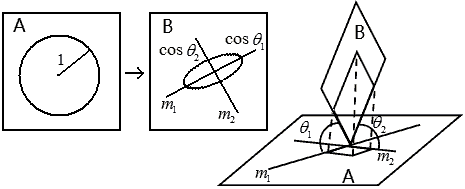
The major and minor axes are perpendicular to each other, so the line $m_1$ when the line-plane angle takes its maximum value is perpendicular to the line $m_2$ when the line-plane angle takes its minimum value. But if we take all lines $m$ on plane $B$ instead of plane $A$, would the two maximum and minimum line-plane angles be different from before? The answer is: no matter which plane you choose first, these two angles are the same, which ensures the definition is well-defined. (Can be proven using linear algebra, omitted)
Let’s look at the familiar 3D space:
- $A, B$ parallel: Any line in $A$ has a line-plane angle of 0° with $B$, so both maximum and minimum values are 0°, $\theta_1=\theta_2=0$; Of course, we can also understand it this way: the unit circle on $A$ projects onto $B$ orthogonally, i.e., size and shape remain unchanged, so $\cos\theta_1=\cos\theta_2=1$.
- $A, B$ perpendicular dihedral angle: Lines in $A$ parallel to their intersection have minimum line-plane angle 0° with $B$, lines in $A$ perpendicular to their intersection have maximum line-plane angle 90° with $B$, so $\theta_1=90°, \theta_2=0$; Another way to think about it: the unit circle on $A$ projects onto $B$ as a line segment of length 2, which we consider an ellipse with semi-major axis 1 and semi-minor axis 0. So $\cos\theta_1=0, \cos\theta_2=1$.
- $A, B$ form a general dihedral angle: Lines in $A$ parallel to their intersection have minimum line-plane angle 0° with $B$, lines in $A$ perpendicular to their intersection have some maximum line-plane angle (i.e., the size of the dihedral angle), so $0<\theta_1<90°, \theta_2=0$.
Since $\theta_2=0$ when $A, B$ form a dihedral angle, we also call $A$ and $B$ semi-parallel, and when $A, B$ form a perpendicular dihedral angle we call it semi-parallel semi-perpendicular, while the original $A, B$ parallel is called absolutely parallel.
Now for the 4D space cases:
- $A, B$ absolutely perpendicular: Since any two lines are perpendicular, any point on plane $A$ projects onto plane $B$ at the point where their perpendiculars meet (like plane $xy$ projecting onto plane $zw$ at the origin), so $\theta_1=\theta_2=90°$.
- $A, B$ in general position: $90°>\theta_1\ge\theta_2>0$.
- Now we have absolutely parallel, semi-parallel, semi-parallel semi-perpendicular, absolutely perpendicular, we surely think of semi-perpendicular: $\theta_1=90°>\theta_2>0$, we’ll see this case right away.
The Hypercube is the Best Friend for Understanding 4D Geometry
Recalling high school solid geometry, we found many line-plane relationships in the cube. Now it’s the hypercube’s turn! There are many parallel projection directions for the hypercube, but I chose one that shows each edge of the 4D cube as equal length, and all eight cubic cells as congruent. We’ll find almost all geometric relationships in this diagram.
This diagram is cleverly constructed but not difficult to draw. First draw an eight-pointed star, then make squares outward from each line of the star, and connect the vertices correctly.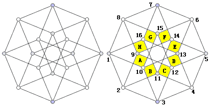
First, we need to find these eight cubic cells. Observing carefully, we can see that once we find these yellow squares marked with letters (they don’t actually exist, only appearing due to overlapping lines in projection), we can find the corresponding cubic cells. For example, the cube corresponding to yellow square A is 9-12-3-2 — 8-15-10-1. For convenience, we’ll use these letters to refer to the cubic cells.
It’s easy to see that A—E, B—F, C—G, D—H are four pairs of non-adjacent cells that are parallel to each other; the distances between vertices have four types: 1, $\sqrt2$, $\sqrt3$, 2. Among them, a pair of vertices with distance 2 are the farthest apart, like 1—5, 2—6, 10—14, 12—16.
Below we only list relationships not sharing a cell:
- Line-plane relationship: different cells (like plane 2-3-12-9 and line 5-6), i.e., neither parallel nor intersecting, we can translate line 5-6 to 12-15, now they intersect and share cell A
- Line-cell relationship: parallel (like cell G and line 3-4)
- Line-cell relationship: intersecting (like cell D and line 6-7 only intersect at point 6)
- Plane-plane relationship: sharing a point (like plane 2-3-12-9 and plane 12-5-6-15 intersect at point 12, and are absolutely perpendicular)
- Plane-plane relationship: semi-parallel, but no common points (like plane 2-3-12-9 and plane 14-5-6-7 have no common elements, and are semi-parallel semi-perpendicular)
- Plane-cell relationship: parallel (like cell D and plane 1-2-11-16)
- Plane-cell relationship: intersecting (like cell D and plane 14-5-6-7 intersect in line 6-15)
- Cell-cell relationship: parallel (like cell D and cell H)
- Cell-cell relationship: intersecting (like cell D and cell E intersect in plane 4-5-6-13)
Others
You might say all I found were square faces, which is boring. Fine, now let’s find some interesting cross-sections of the hypercube and positional relationships of “oblique planes”.
Hypercube Cross-sections
Verifying that four points determine a cell: Choosing any four non-coplanar vertices in the hypercube can determine a cell. Just like when we do solid geometry, sometimes the tetrahedral cell formed by these four vertices is not a complete cross-section in the hypercube (note, this is a 3D face here), we can “complete the shape” by supplementing its cross-section cell’s vertices. For example, the cell determined by points 1, 15, 9, 13 (marked in red) (let’s call it cell $\Pi$) needs “shape completion”. We notice that vertices 9 and 13 are a pair of opposite vertices (i.e., farthest apart, distance 2), so line segment 9-13 passes through the hypercube’s center (temporarily denoted as point O). So cell $\Pi$ passes through point O. The line containing point 1 and point O should also belong to cell $\Pi$, and since points 1, O, and 5 are collinear, point 5 also belongs to cell $\Pi$. Similarly, we know that points 15, O, and 11 are also collinear, so point 11 also belongs to cell $\Pi$. (Supplemented points are marked in black) Connect these points (note that opposite vertices cannot be connected, as the formed body diagonal is inside the hypercube, not on the boundary of the cross-section). Calculating further, we find that except for these opposite vertices, the distance between any two points is $\sqrt{2}$. This shows that cell $\Pi$ intersects all eight cells of the hypercube, cutting the hypercube into a regular octahedral cell.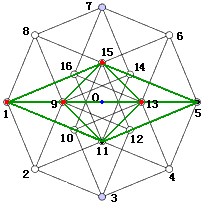
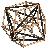
How do you know your shape is complete? If all the faces of your cross-section figure are on the hypercube’s surface — within the eight cubic cells — i.e., all edges are within the hypercube’s 24 square faces, then the shape completion is done.
Choosing any four non-coplanar vertices in the hypercube can determine cells of many shapes. Here I’ve listed some on the left side of the figure below: (1) diagonal cell (like 1-8-15-5) (2) cubic cell (like 5-7-8-15) (3) regular tetrahedron from truncation (like 1-11-13-7) (4) maximum cross-section regular octahedron (like 1-7-9-13) (5) triangular prism from edge truncation (like 1-2-4-7)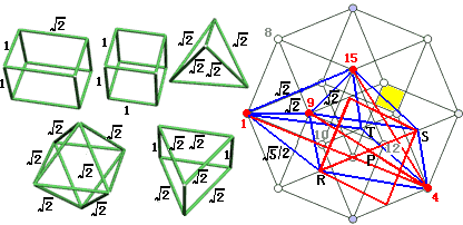
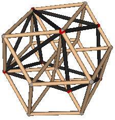
But what’s worth mentioning is that when choosing any four non-coplanar vertices in the hypercube to determine a cell, the supplemented vertices after shape completion might not be vertices of the hypercube. For example, the cell $\Gamma$ determined by points 1, 9, 4, 15 in the upper right figure. The three supplemented vertices are actually edge midpoints! Specific completion method: Since line segment 4-9 passes through the center of cell C (temporarily denoted as point P), through point P make a plane parallel to face 1-8-15-10 intersecting cell C in a square (marked in pink), which produces points R and S. Then point R (midpoint of line segment 2-11) and S (midpoint of line segment 12-5) are in cell $\Gamma$. Reason: Since RS∥line 1-15, therefore R, P, S, 1, 15 are coplanar. Since 1, 15, P are in cell $\Gamma$, therefore R, S are also in cell $\Gamma$. Having supplemented points R and S, the remaining point T can be easily supplemented using the parallel line method. Finally, let’s observe this complete cross-section cell. It’s a heptahedron consisting of three rhombi with side length $\sqrt{5}/2$, one equilateral triangle with side length $\sqrt{2}$, and three isosceles triangles. Having seven faces means cell $\Gamma$ intersects seven cells, with one cell not intersecting, which is cell E (shown separately in yellow here)
Oblique Planes
- Absolutely Perpendicular
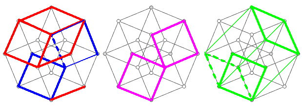
Please find the normal plane to face 1-3-13 (the red face on the left side of the figure below).
Approach: As long as we find two intersecting lines both perpendicular to this plane, the plane determined by those intersecting lines is absolutely perpendicular to this plane. (This is a good criterion for absolute perpendicularity!)
Since face 1-3-13 is in cell B, we might as well find a normal line to face 1-3-13 within cell B, which is 10-11 (easily proven by the three perpendiculars theorem in solid geometry), so line 10-11 is one line we’re looking for.
Since cell B is perpendicular to line 10-15, face 1-3-13 within cell B is also perpendicular to line 10-15. Thus, the plane 10-11-14-15 determined by lines 10-15 and 10-11 is the required normal plane. (Blue face) Their only common point is on line segment 10-11 at the one-third point closer to 10.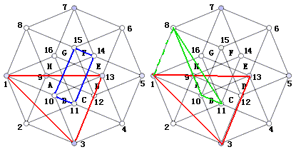
- Semi-perpendicular
As shown on the right side of the figure above, face 1-3-13 and face 10-11-8 are semi-perpendicular: line 10-11 is perpendicular to face 1-3-13, but the projection of point 8 onto face 1-3-13 is 1, obviously not falling on their only common point. So the line connecting point 8 and the common point is not perpendicular to face 1-3-13. Therefore these two planes are semi-perpendicular, $\theta_1=90°$, but how do we find the value of $\theta_2$? It’s a minimum value, and it seems impossible to see from the diagram.
It seems we can’t proceed further now. But recalling high school solid geometry, when finding the angle between two planes (of course, dihedral angle), the teacher also taught another method: projection area theorem.
Thinking question: Please draw the normal plane (absolutely perpendicular plane) to the green plane in the upper right figure.
Generalization of the Projection Area Theorem
The projection area theorem states that the projected area of a plane figure equals the area S of the projected figure multiplied by the cosine of the angle between the plane containing the figure and the projection plane.
This is familiar to us in 3D space. Here’s a rough proof outline:
We choose a specially shaped projected figure: a square. The position is also special: one side of the square is chosen parallel to the intersection of the two planes, and the other side is naturally perpendicular to this intersection. After projection, the side parallel to the intersection remains unchanged in length, while the side perpendicular to the intersection becomes $\cos\theta$ times its original length, where $\theta$ is the dihedral angle between the two planes, so the square area becomes $\cos\theta$ times the original. We divide other irregular shapes into countless such small squares, so the overall area also satisfies the $\cos\theta$ times relationship.
It’s the same in 4D, except when choosing square area elements for projection, both sides in the maximum and minimum angle directions (remember? these two directions are exactly perpendicular) must be multiplied by the cosine of the angle, causing the area to become $\cos\theta_1\cos\theta_2$ times the original. That is:
The projection area theorem in 4D: The projected area of a plane figure equals the area S of the projected figure multiplied by the product of the cosines of the angles $\theta_1, \theta_2$ between the plane containing the figure and the projection plane.
Using this magical method, we can only get $\cos\theta_1\cos\theta_2$, obviously still lacking conditions. It seems we must use algebra to find angles. Later we’ll see that the vector method is no longer suitable for 4D geometry, and the vector method needs to be upgraded. In the upgraded vector method, we’ll still need to use the generalization of the projection area theorem.