4D World (IX): Aircraft Design
What would aircraft structures look like in a four-dimensional world? In this article, we’ll explore some possible design approaches from 4D fans to drones to large passenger aircraft.
Flight Simulators
- 4D Drone Simulator (open with PC Chrome browser)
- 4D Airliner Flight Simulator (open with PC Chrome browser)
4D Fans
Let’s start with a warm-up topic: designing a 4D fan that can blow air. As before, we first analyze the 3D case, looking at front and side views of a 3D fan.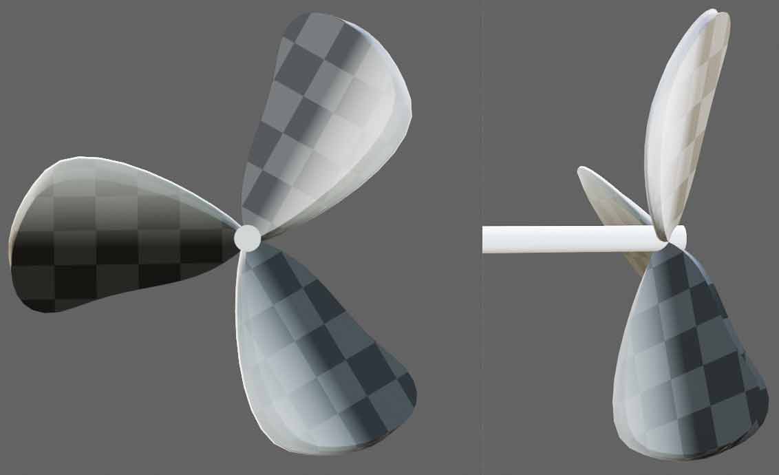
Note that the compressed dimension in the front view can be viewed by color brightness. This is to warm up for using the same method to view 4D fans later. The key to a fan producing airflow is that the blades are tilted at an angle to the rotational direction, so when the blades rotate they push air away, creating airflow.

How would a 4D fan produce airflow through rotation? The airflow principle diagram above can actually be understood as a one-dimensional line segment “blade” in a 2D world that has been dimensionally extended through a series of complex operations (Extrusion, then copying blades and bending to change linear airflow structure into rotational airflow). This inspires us that the simplest 4D fan is to extrude a 3D figure to get a 4D version. Such a 4D fan’s swept region changes from cylinder to cubinder. Although the cubinder itself has equivalent heights in both directions, the 4D fan’s tilt eliminates this symmetry. Whether a fan rotating in the xy plane blows air in the z or w direction depends entirely on how the blades are tilted, and the blade thickness in these two directions also differs: the 3D blades before extruion themselves can be very thin, but the length in the extusion direction shouldn’t be too short, otherwise it reduces the surface volume of blade-air contact.
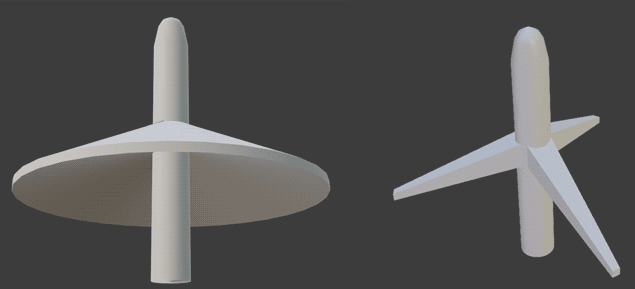
Now we can draw two orthogonal projection views of the 4D fan containing the rotation plane: (3D object projections are 2D, so 4D object projections are 3D - we’ll be drawing various 3D views of 4D objects throughout!)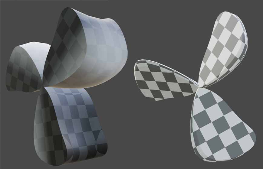
For the 4D fan airflow front view (left), you can see this is a prismatic object, but the projection removes the fan’s tilted airflow direction - the blade tilt can be seen from the light-dark coloring. For the extrusion direction front view (right), it projects away the extrusion direction. The “base cell” is a flat 3D fan figure, and the fourth compressed height is the same, so you can see the light-dark shading is uniform.
You might also notice a small detail: from the 4D fan airflow front view (left), you can see the fan blades aren’t standard cylinders - they seem slightly concave in the middle. This is designed to better funnel airflow to the center to drive the blades. Since I haven’t yet written 4D fluid simulation, I can’t provide precise optimization schemes for the shape.
Double Rotation Fans?
You might think this extruded blade approach is too crude - are there other more ideal fan design schemes? Unfortunately, rotation is a 2D effect. I can’t figure out how to let a spherinder-shaped fan works. At most, we could cut out some parts of extruded blades to make it look like a spherinder, but the principle would still be cubinder-based, and smoothing would lose some contact surface volume in high linear velocity regions, which is bad for blowing airflow.
You might say 4D space also has double rotation - could we make fans with more beautiful symmetry? If we apply a hypersphere with double rotation and attach tilted blades to its surface, it’s conceivable that due to the symmetry of double rotation, this thing would blow air in all directions - it’s no longer a fan but becomes a vacuum pump, or if rotated in reverse, a compressor that sucks air in from all directions. Hard to imagine? Its 3D analogy is this: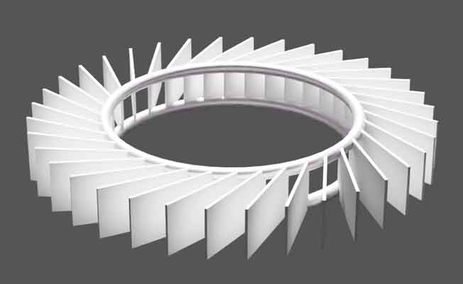
Ignoring the air intake channels, this thing is actually 2D. We can even use concentric circle cross-section animation to describe it to 1D creaters: imagine a circle centered at the vacuum pump/compressor rotation center, starting from zero radius and gradually growing. When the radius is very small, nothing is intersected. When the radius increases to the inner ring size, the entire circle becomes filled with the inner ring. As radius grows larger, the inner ring is no longer intersected but the blades are, creating many points on the intersection circle that rotate around the circumference as the intersection circle radius increases. When the intersection circle radius exceeds the distance from the blade tips to the center, everything disappears. 1D beings only need to understand what happens on the 1D circumference, which is easy for them: just cut open the circle and unfold it into a line segment.

Similarly, a 4D Hopf fan intersects the inner ring, which fills the entire 3D sphere surface. But unlike 2D where cutting disconnects continuity, this 3D sphere surface can be made hollow for material savings or airflow convenience. As the intersecting hypersphere continues to grow, the inner ring disappears and blades are intersected. If blades are made as tilted cylinders, many circular discs with normal vectors along double rotation trajectories (i.e., Hopf fibers) appear. As radius continues increasing, these discs move along the double rotation trajectory direction. When the intersecting hypersphere radius exceeds the distance from blade tips to center, everything disappears.
This Hopf vacuum pump/compressor is theoretically usable but not very practical. I believe 4D people wouldn’t actually use such contraptions - a sealed container with a tube for direct vacuum suction would be much more convenient. If there were a fifth dimension, we could cylindrify this Hopf fan and tilt it in the fifth dimension to get a true fan with swept region as a glominder (i.e. prism with hypersphere base), blowing air in the fifth direction.
4D Drone Design
Propellers work on the same principle as fans. According to Newton’s third law, expelled airflow creates reaction thrust on the blades. Current mainstream drones in our world use quadcopter designs, relying on four propellers rotating to generate lift for flight. If we extend quadcopters to 4D, how to design, control, and operate them? Still, let’s first see how 3D quadcopters work.
3D Quadcopter Operating Principles
A quadcopter is a cross-shaped frame with four propellers at the ends. By properly controlling rotation speed, we can control the difference between rotation-generated lift and gravity to achieve ascent, descent, or hovering. Horizontal movement is slightly more complex: for forward movement, reducing front propeller speed and increasing rear propeller speed disrupts the balance, subjecting it to rotational torque that tilts the drone forward. The lift generated by all propellers then has a forward-tilted component, propelling the drone to accelerate forward. Similarly, deceleration or rearward acceleration requires adjusting speeds to make the drone tilt backward. In other words, we control rotational torque through propeller speed differences to control drone tilt attitude, then use tilt angle to control drone translational acceleration to make the drone move.

As you can imagine, manually controlling individual motor speeds to tilt the aircraft for translation makes stable flight very difficult (you can try this in my 4D drone simulator without auto mode enabled). Generally, automatic control technology uses negative feedback to increase stability, and pilots don’t directly control propeller motor speeds but rather aircraft tilt angles or even direct aircraft velocity target values, with control systems automatically adjusting motor outputs to achieve preset values. Both 3D and the 4D aircraft we’ll design need automatic control systems with roughly similar principles - we won’t elaborate further.
Let’s look at horizontal rotation attitude control. Note that propeller rotation reaction forces cause the aircraft to rotate in the opposite direction (reaction torque), so engineers deliberately design two propellers to rotate clockwise and the other two counterclockwise to prevent the aircraft from spinning immediately upon takeoff. If we want deliberate aircraft rotation, we just adjust speed differences between sides. This reaction torque exists for all propeller aircraft: for example, if a helicopter only has the top “big fan” rotating, the entire fuselage experiences reaction forces and starts spinning madly. To counteract rotation, engineers add tail rotors to helicopters, applying opposite torque to cancel rotation.
Finally, let’s summarize the three motion control principles of quadcopters using some diagrams from Wikipedia:


4D Propellers
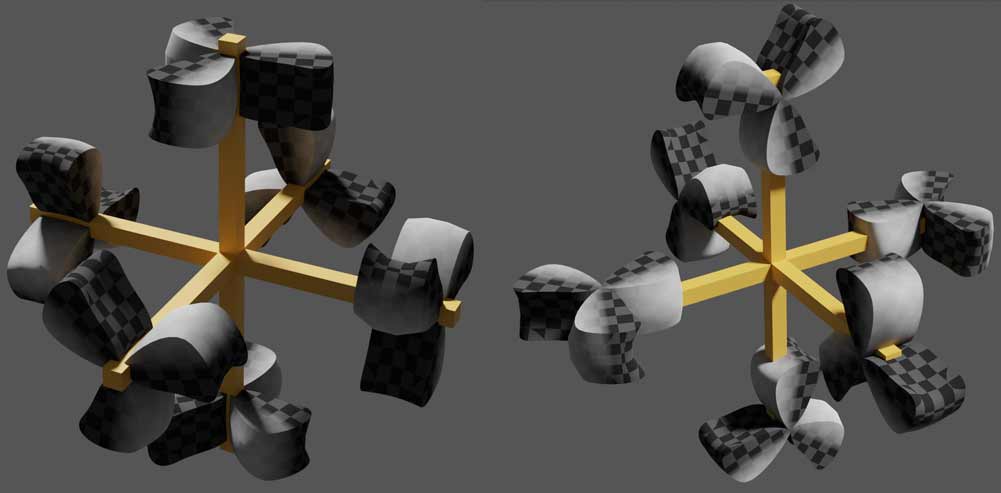
How should 4D propellers be arranged and installed on drones? The most obvious way is to analogize quadcopters to hexacopters, installing one propeller at each end. Note that propeller swept regions are now cubinders, with one height aligned with the vertical direction for generating lift. The orientation of the base (i.e., top view) cylinder can have different choices - for instance, here are two relatively symmetric design schemes. It seems that the right diagram shows the drone frame intersecting the propeller blades incorrectly - There’s no intersecting at all. This is just the aircraft’s top view. Like 3D drones, propeller height is greater than frame height, so they don’t actually intersect. The propellers actually have vertical shafts connected to the frame.
Let’s look at attitude control. Ascent/descent and translation are very similar to 3D, controlled by different proportions of lift generated by six propellers - nothing special to mention. But horizontal rotation is different. The 4D horizontal plane is actually a 3D cell, so horizontal rotation has 3 degrees of freedom, and it relies on propeller-generated torque. All torques must cancel to maintain aircraft stillness. So we follow the 3D approach, setting two propellers of the same orientation to rotate in opposite directions to maintain stillness. However, when we want aircraft translation, speed differences between side propellers not only tilt the aircraft but also prevent torques from canceling, causing aircraft rotation. This means if we adopt the six-axis aircraft design above, horizontal rotation couples with vertical tilt operations responsible for translation - we can’t independently control either behavior.
Actually, just two propellers in the same plane cannot accomplish all operations: independently controlling ascent/descent, translation, and horizontal rotation requires three equations to solve for two unknowns (two propeller speeds), which clearly has no solution. The two design schemes above cannot be adopted. All 4 propellers of 3D quadcopters are coplanar, so this problem doesn’t exist.
To control all rotational degrees of freedom of 4D aircraft, we must increase the number of propellers in the same rotational plane. Since rotational attitude control has three degrees of freedom, we need three groups of oriented propellers. For instance, the following design with all propellers in one plane cannot control the aircraft’s rotation in the red and blue arrow directions shown, so the design below is also unusable. 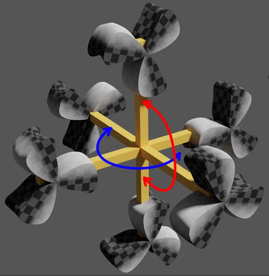
Two Typical 4D Aircraft Design Schemes
While three equations tell us three propellers might suffice, linear equations don’t guarantee full rank solutions, and control algorithms become very complex. It’s better to simply install counter-rotating propellers for each propeller to cancel torque. If spin is desired, we can control speed differences in these propeller pairs to generate small torques. This changes six propellers on six axes to 12 propellers. One typical design scheme is: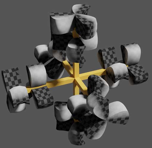
Actually, this torque-canceling idea has long been used in the real 3D world, called coaxial counter-rotating propellers. According to Wikipedia, coaxial counter-rotating propellers can cancel rotational air flow, reduce energy loss, and improve efficiency, but the downside is greater noise. Note that this 4D design differs from 3D coaxial counter-rotating propellers: 3D versions have two propellers side-by-side in the airflow direction, while 4D versions are side-by-side in the propeller extrusion direction - meaning the same airflow isn’t simultaneously affected by two counter-rotating propellers.
If you still find counter-rotation unfavorable, you can also consider spreading four propellers in a plane to get a very beautiful 12-axis aircraft arranged at cube edge centers: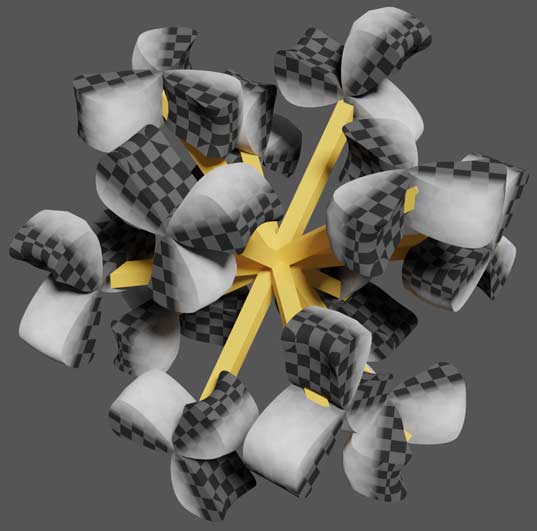
This is the second typical 4D aircraft design scheme, where each propeller blade’s rotation plane forms a 45-degree angle with its connecting axis. Feel free to comment if you come up with other more elegant design ideas!
Tesserxel engine’s examples includes a quadcopter simulation scene using typical scheme 1. Link here. You can try the operation hints in the left sidebar first, with detailed gameplay tutorials coming later.
4D Airliner
Let’s look at another aircraft structure: fixed-wing aircraft. These are the only aircraft most people have the chance to ride. Following convention, let’s first supplement relevant professional knowledge about 3D aircraft. First, we’ll look at 2D three-view drawings of 3D aircraft, then analogize to 3D four-view drawings of 4D aircraft. For example, here’s a Boeing 737 three-view drawing I found online.
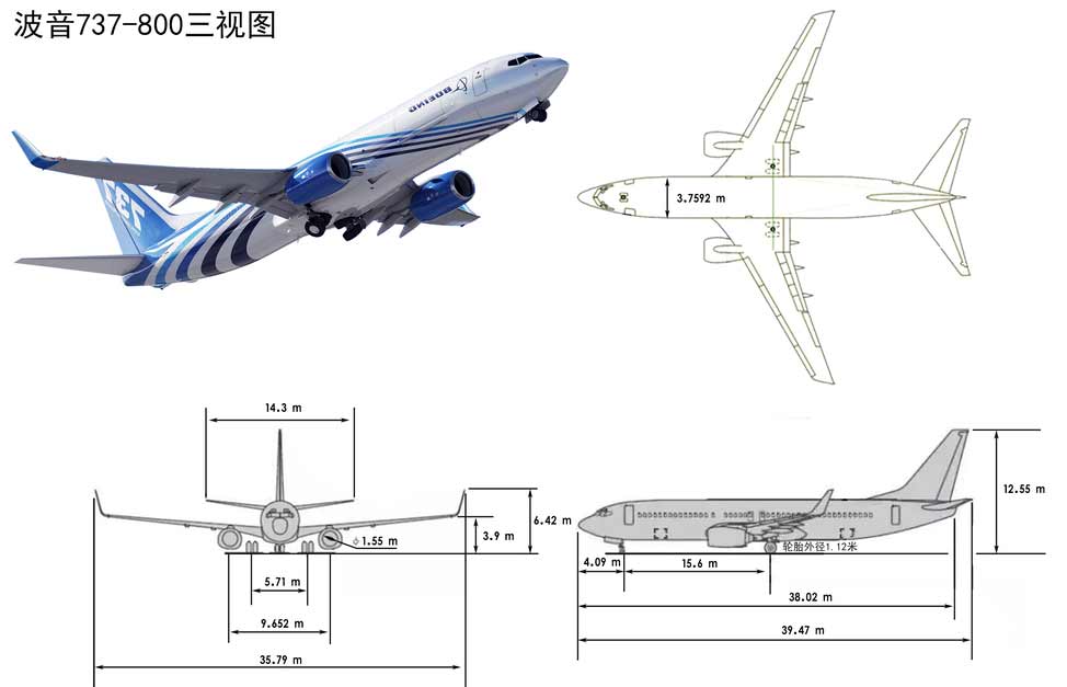
Fixed-wing aircraft engines only provide forward thrust, relying on wing shape to create pressure differences between upper and lower airflow for lift. Aircraft attitude control uses several groups of movable panels (technical term: control surfaces) attached to wing and tail tips.
3D Aircraft Control
Elevator controls pitch angle
The elevator attaches to horizontal tail surfaces via hinges, controlling lift by rotating up/down to change the angle with airflow.
Rudder controls yaw angle
The rudder attaches to vertical tail surfaces, controlling direction by moving left/right.
Ailerons control roll angle
Ailerons attach to wings and can rotate up/down like elevators. When one aileron goes up and the other down, aircraft roll attitude is controlled.
Why does controlling these control surface rotations change aircraft attitude as desired? These panels are generally very thin with vastly different air resistance in various directions. Tilting these panels changes their forces in airflow, subjecting the originally force-balanced aircraft to translational forces and rotational torques that jointly adjust aircraft attitude. Note that all control surfaces attach to the aircraft, so these pitch, yaw, and roll controls are all relative to the aircraft’s own coordinate system. These directions rotate with aircraft rotation, not the ground coordinate system used to describe aircraft attitude later.
4D Aircraft Design
In the following text I will present possible design schemes for fuselage, wings, engines, landing gear, and other components in order. Since my flight dynamics knowledge was recently crammed, flight dynamics experts are welcome to correct possible errors in the text.
Fuselage Design Scheme
3D aircraft fuselages approximate cylinders with streamlined nose designs. The simplest 4D analog is rotating the 3D fuselage to create revolutional 4D fuselage shape. Note that 3D aircraft noses aren’t rotationally symmetric - ther are only left-right symmetric. So we can use the central vertical symmetry plane as the axis to construct a 4D solid of revolution. This creates a 4D fuselage approximating a spherinder.
How should passenger seats and windows be arranged in the cabin? Since passengers are also 4D beings, let’s start with seat structure. Assuming 4D humans are also upright-walking beings, seats first need one direction as a backrest, with the opposite direction open for legs, and all other sides around as armrests - this works regardless of where or how many arms 4D people have. In addition, seats must face forward.
Actually, seat shape doesn’t matter much - just as our real world has square stools and round stools that can both be upgraded to chairs by adding backrests. So 4D seat shapes can be very diverse, from cubes to cylinders to spheres. Since square stools can’t sit close to aircraft windows (though maybe that doesn’t matter), cabins might prefer cylindrical/hexagonal seat arrangement designs (though cylindrical gaps might create cleaning difficulties).
Aircraft windows are distributed all around, with larger cockpit windows for good visibility, looking somewhat like spaceships: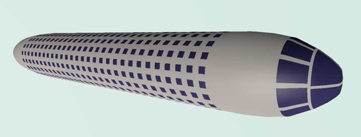
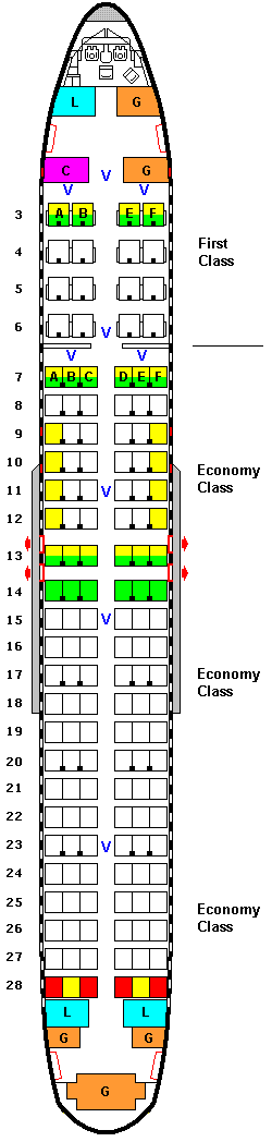
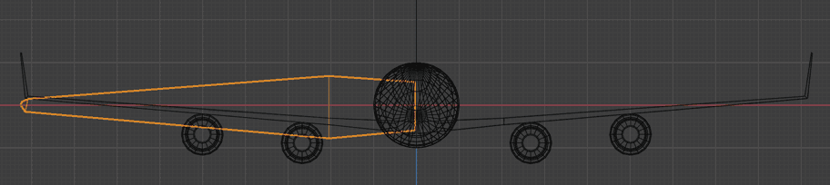
Note that “real” 4D windows are all 3D rectangular cells, not just 2D grids. All the diagrams above only show cross-sections of aircraft with height direction removed, analogous to 3D diagrams like this:
Aircraft Attitude Terminology
Before continuing with attitude control, let’s clarify 4D aircraft attitude terminology.
Yaw angle: Aircraft heading. Since 4D ground is 3D, yaw angle also needs two directions for description. 3D headings are generally described as “north by east xx degrees” or “west by south xxx degrees”. We introduced the Hopf latitude-longitude system used by 4D people in 4D World (I): Planetary Day-Night Seasons, so here we only supplement direction description. We can reference spherical coordinates by first describing the azimuth angle of this direction projected on the meridional plane, then describing the angle between this direction and the meridional plane. For example, the aircraft in the diagram below has yaw angle “west by garp 12 degrees by north 39 degrees”. Why don’t 4D people first determine east-west-north-south directions then angles with marp-garp directions? This is because east-west and marp-garp directions are two equivalent latitude line directions, with only north-south being the meridional direction, so they habitually group east-west-marp-garp together.
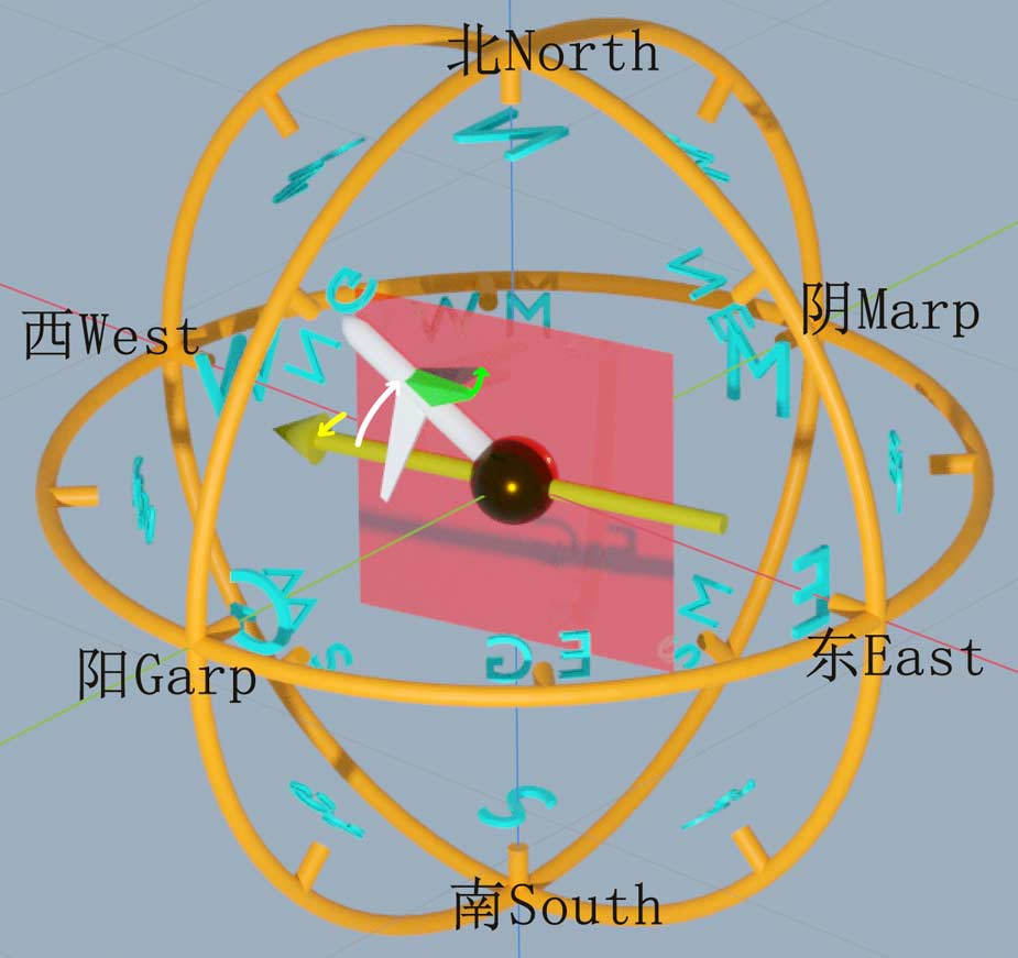
Spin angle: On 3D ground, besides two degrees of freedom for orientation, there’s one degree of freedom for spin orientation. Actually, spin angle and two yaw angles together constitute three degrees of freedom describing object rotational orientation in 3D space, representable using standard roll-yaw-pitch Euler angles. Here pitch corresponds to the angle between aircraft nose and meridional plane, yaw corresponds to azimuth angle on meridional plane, and roll corresponds to spin angle. For example, we can use an aircraft wing or cabin door as reference (the green-highlighted wing selected above, which we’ll discuss in detail later), taking the angle between the plane formed by it, the aircraft nose, and north-south direction (red plane in diagram) as spin angle (green angle marked above). Note that if aircraft yaw angle is due north, the red plane cannot be formed, and spin angle needs other representations - this is the inherent “gimbal lock” effect of Euler angle for describing orientation.
Pitch angle: The first three angles are all aircraft orientation in 3D ground. True pitch angle is the angle between aircraft nose and horizontal ground, which cannot be marked in the top view projection above.
Roll angle: Unlike 3D aircraft that can only roll left-right, 4D aircraft can roll in left-right and ana-kata degrees of freedom. There are two ways to describe roll: one describes angles between aircraft left-right direction and ana-kata with horizontal cell separately, another first describes which direction tilts most severely (like gradient), then uses a tilt angle to describe tilt amount.
Wing Design Scheme
4D wings are hardest to imagine. Let’s start from 3D aircraft three-view drawings to try drawing 4D aircraft four-view drawings.
Top view has no gravity direction, 3D only has aircraft forward-backward direction and perpendicular lateral direction, while 4D has forward direction and mutually perpendicular left-right/ana-kata lateral directions. In 4D space direction identification, we said 4D lateral is actually a circle, so when designing wings, we also go around the aircraft forward direction. There are two schemes:
Like handling fuselage, directly rotate 3D aircraft top view around symmetry axis to dimensionally extend to 4D aircraft three-view drawing. Actually, any 3D figure with symmetry plane can be analogized to 4D by rotating around the symmetry plane.
Install n wings distributed at regular n-gon’s vertices.
The first scheme is easiest to imagine, but this integrated wing going all around is easily stressed by different directional forces accumulating stress, and it’s also bad for material savings and weight reduction. So “actual” 4D aircraft generally adopt the second scheme. Like wind turbine blades, three wings are sufficient to provide lift while keeping aircraft balanced, and more wings cause control systems become more complex. So “actual” 4D aircraft mostly use three wings.
December 2024 Update: Someone on the higherspace forum pointed out that the first scheme isn’t entirely worthless: directly rotating one full revolution creates wings with large windward surface area. Even without very long wingspan, it can achieve the same lift while being light and strong. Compared to the second scheme of distributing n wings, its shape is more “rounded” and might significantly suppress wingtip vortices and tail turbulence, improving aircraft stability (P.S. winglets on our aircraft wing tips are used to suppress wingtip vortices). However, since we’re not fluid dynamics experts and can’t perform fluid simulations, it’s hard to say which scheme “real” 4D aircraft would prefer. Maybe different aircraft types like civil airliners, high-maneuverability fighters, and supersonic aircraft would choose different schemes based on comprehensive considerations.
This article continues using the second scheme for design. How to design wing shape? Starting from 3D aircraft wings, the most direct method is extrusion, or thickening. Note this extrusion can’t be too thin, otherwise contact volume with airflow (note this is 3D contact of 4D shape’s surfaces!) is too small to generate sufficient lift. But extrusion thickness has an upper limit - at least not exceeding the width connecting to fuselage, otherwise wing corners protrude causing great drag. Direct extrusion is a poor shape. We can improve it by making extrusion thickness non-uniform: narrower near fuselage for smooth connection, thicker outward for increased airflow contact surface volume, then thinner further out for improved stress distribution. This creates an aerodynamically good irregular 4D wing.
Engine Design Scheme
3D aircraft engines hang under wings - same for 4D aircraft. 3D aircraft engine structure is actually very complex. While 4D turbines overall use 3D helical turbine extrusion for construction, considering combustion chambers need pressurization, rotational radius and extrusion amount would be both reduced at engine’s tail part. Internal pressurization devices and power transmission systems are too complex, far beyond this article’s scope. Here we only consider engine installation orientation issues.
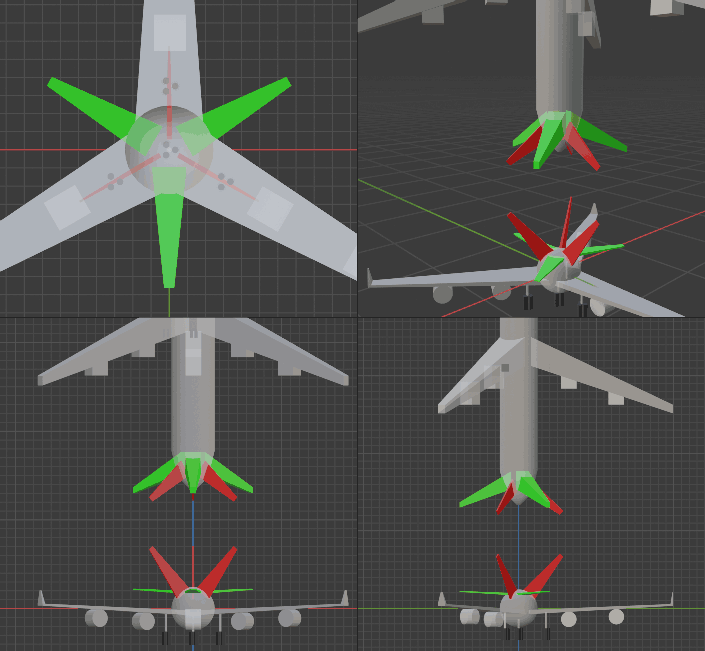
For 3D aircraft, engines must face forward to propel aircraft - no other choice. 4D aircraft are different. While engines must face forward, their intake cross-section cell is cylindrical, and cylinder orientation can be choiced. Below are several orientation scheme views.
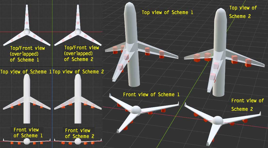
Let’s focus on the right perspective views showing top and front orthogonal projections of two schemes. The left upper and lower grids show 2D front views that are projections of projections of the right 3D views, also for reference. Note top view compresses vertical direction, front view compresses front-back direction.
From top view, all engines are front-back cylinders because engines must generate forward thrust - this is airflow intake/exhaust direction. Note wings are made transparent so engines appear embedded in wings, but they don’t actually overlap - height direction is projected away, engines hang below wings.
Scheme 1 front view shows engines as cylindrical - this cylinder is engine intake cross-section shape, with engine rotation plane in left-right/ana-kata directions.
Scheme 2 front view shows engine intake cross-section also cylindrical, with engine rotation planes oriented differently on different wings but all including vertical direction.
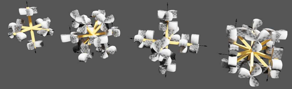
How to choose between schemes? Like drones, we need to consider torque balance. Scheme 2 most easily achieves torque balance, with rotation directions marked below. Scheme 1 can’t cancel torque through rotation direction arrangement if three engines have same speed, so we don’t adopt scheme 1 but scheme 2.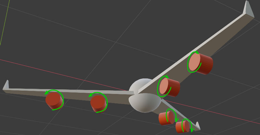
Landing Gear Design Scheme
3D aircraft have many landing gear design schemes. We only analyze the common airliner configuration of one nose wheel plus one wheel per wing, similar to the four-wheel vehicle discussed in 4D transportation, with stable tetrahedral structure that won’t tip over.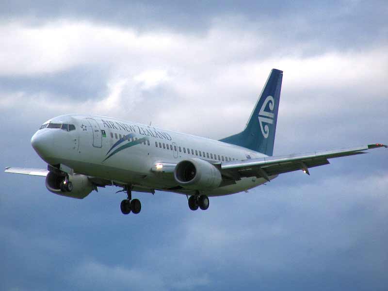
Notice that each wheel of large 3D aircraft is actually a group of wheels for stability and load distribution. Similarly, we can replace each 4D aircraft wheel with three wheels in equilateral triangle arrangement, totaling 12 wheels.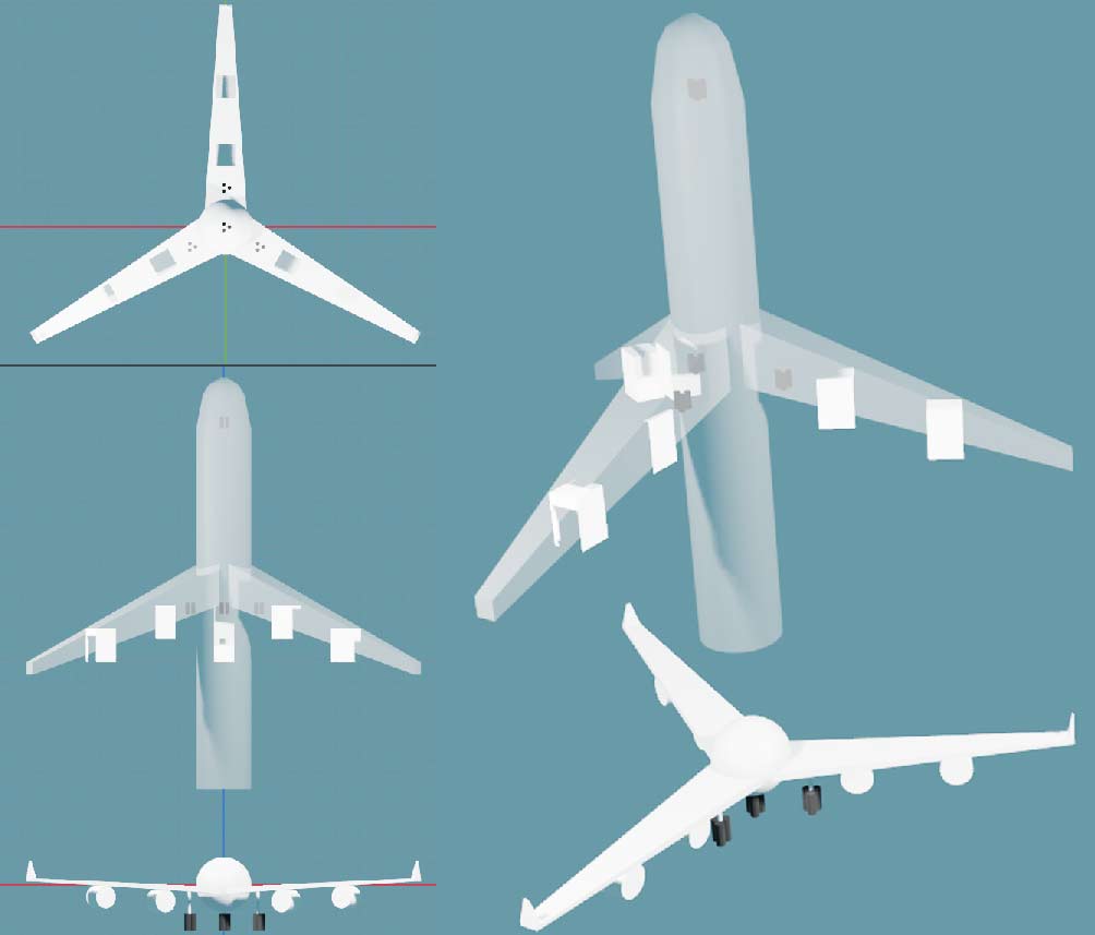
Wheel shapes can approximate cubinders, duocylinders, or even spheritorus, as long as their rotation plane is vertical and forward directions for rolling. Note the above diagram only shows top and front views, so neither view faces the circular side of wheels directly - both are side views projecting as columns.
Finally, let’s see how aircraft turn while taxiing by controlling wheels. If nose wheels have steering systems, they can turn like tricycle front wheels. Without steering systems, we can turn through unbalanced rear wheel braking: just brake whichever wheel corresponds to the desired turn direction. But for arbitrary direction turns, we need more than one wheel braking - we control various wheel brake proportions using vector composition to get the final desired turn direction. We won’t elaborate further here.
Tail Design
3D aircraft tails have horizontal and vertical stabilizers. Horizontal stabilizers are similar to aircraft wings but smaller, with elevators connected at the tail end for adjusting aircraft pitch angle and maintaining balance with wings. Vertical stabilizers have rudders and stabilize aircraft yaw.
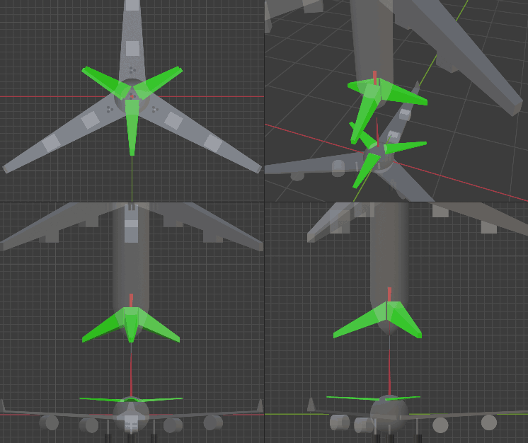
4D aircraft tails can also have horizontal stabilizers (cells) and vertical stabilizers (cells). Horizontal stabilizers have elevators and can be made as three pieces distributed at 120 degrees like wings. Distribution angles have two choices: align with wings or offset 60 degrees from wings (see diagram below). I don’t know the pros/cons of these schemes (seeking aerodynamics expert for help) , I just think offsetting looks better.
Vertical stabilizers differ greatly from 3D: if we imitate 3D by directly installing tail surfaces on aircraft top extending in vertical and front-back directions while being thin in other directions, it becomes a 2D surface rather than 3D cell. While we can imagine controlling aircraft’s two degrees of freedom steering by having tail rudders rotate through ball-joint-like two-degree-of-freedom hinges, its aerodynamic surface volume is pitifully small. Analogizing to 3D, imagine a wire moving in a wind tunnel - while it can have angles with fluid and be blown to get push/pull forces, trying to use such tiny force to adjust and control entire aircraft attitude is too hard. So the scheme below cannot be adopted.
Vertical stabilizers must be dimensionally extended. Common extension methods are extrusion and solids of revolution. Since it’s on aircraft top, already lying on the symmetric rotation surface, it can’t gain fourth-dimensional thickness through rotation, so only extrusion extension works. Which direction to cylindrify? We must understand vertical stabilizer functions to answer this.
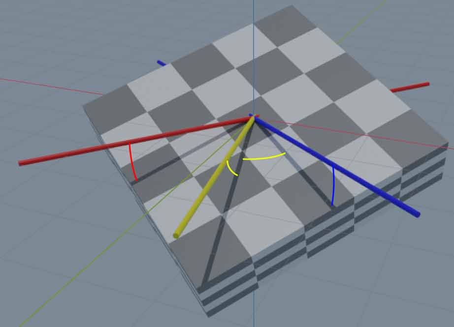
Let’s first look at 3D situations. From front-back view (projection compressing front-back direction), we see they can suppress three rotational directions: yaw rotation sweeps vertical stabilizers (roughly speaking, when a surface moves toward its normal direction, it experiences large resistance, suppressing rotation - this may be unprofessional explanation, sorry…), pitch angle changes sweep horizontal stabilizers, roll angle changes sweep both surfaces.

Similarly, we want 4D tails to suppress all rotational degrees of freedom. We divide 4D rotation into two parts: one part like yaw and pitch that rotates nose-tail orientation, another part like roll that keeps nose-tail stationary (like using them as axis) for rotation. When rotation angles are small, nose-tail orientation rotation appears as translation in rear view, corresponding to two-direction yaw and pitch angle changes; nose-tail stationary rotation appears as three-degree-of-freedom 3D rotation around center in rear view, corresponding to two-degree-of-freedom roll and spin angle changes.
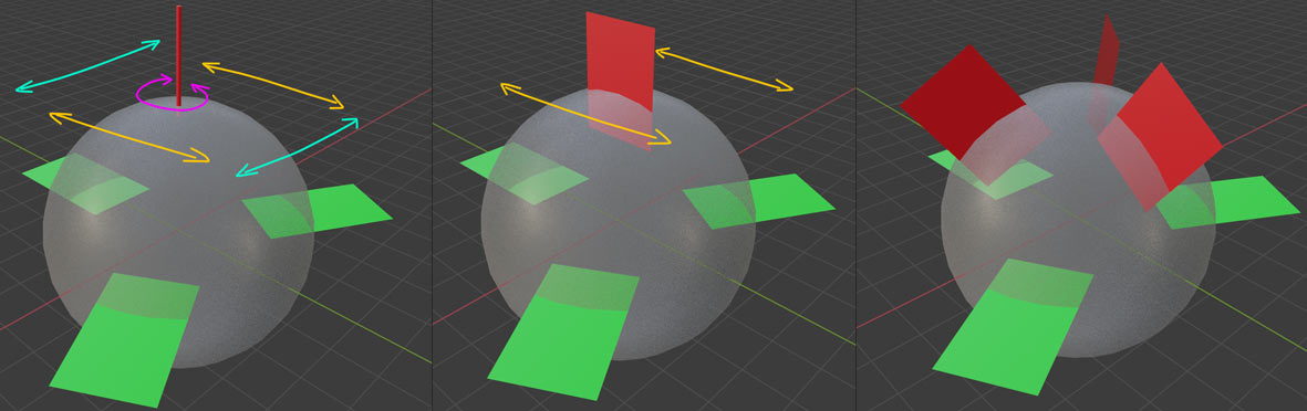
As shown leftmost above, horizontal stabilizers only suppress up-down movement (pitch angle change) and two-degree-of-freedom roll. Spin and two-degree-of-freedom yaw cannot be suppressed. If vertical stabilizers only cylindrify in one direction (middle diagram), that direction’s yaw still cannot be suppressed. We can make three-direction cylindrified vertical stabilizers like horizontal stabilizers (rightmost), suppressing any rotational degree of freedom. Note vertical stabilizers no longer need to be at aircraft top like 3D aircraft.
Vertical stabilizers also importantly control yaw angle. With three vertical stabilizers now, we can make three one-degree-of-freedom normal hinges, controlling three hinges to compose final desired yaw direction. How do hinges specifically work? Top view better observes hinge movement. For example, below diagram shows one vertical stabilizer’s rudder deflecting - during aircraft flight, the aircraft will yaw toward that stabilizer’s deflection direction: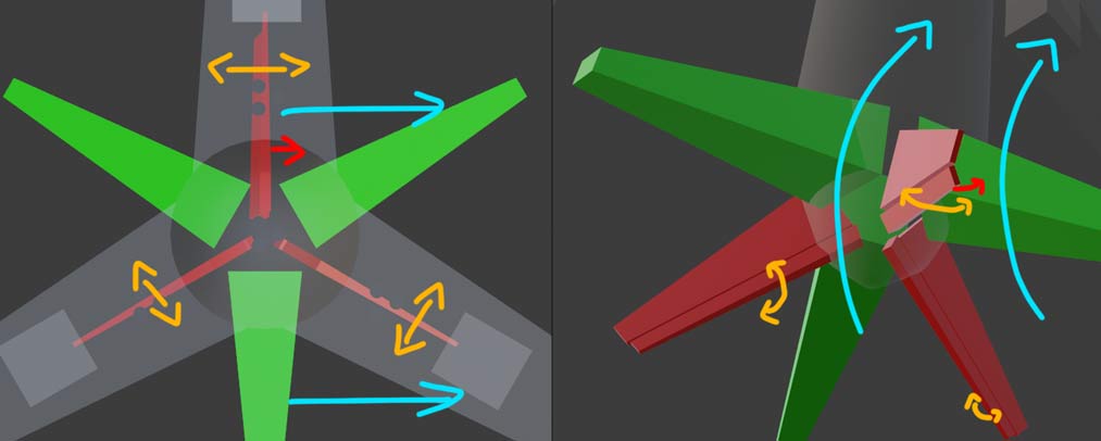
With three controllable rudders but only two yaw angle degrees of freedom, is the extra degree of freedom useless? Actually, this extra degree of freedom lets us control not only yaw but also independent spin. For example, the configuration below won’t make aircraft yaw but will cause aircraft spin, also indicating 4D aircraft need exactly three vertical stabilizers.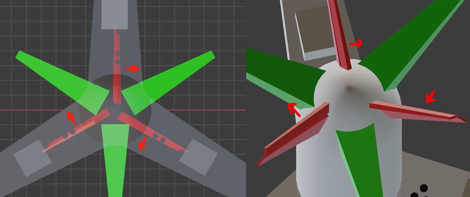
Conclusion
Here, we’ve shown the design schemes for all main components of 4D aircraft. While we showed 4D aircraft top and front views, side view of 4D aircraft is never showed - we’ll leave this as an exercise for readers. The answer can be found in Tesserxel’s 4D aircraft scene, with link here. By the way, Tesserxel’s 4D aircraft scene lets you control 4D aircraft taxi, takeoff, and landing (providing several different difficulty runway directions for landing practice). The next article will introduce specific operation tutorials for 4d aircraft and drone. We’ll also reveal 4D aircraft’s four-view and six-view drawings.