Build Digital Circuits with Hutton32 (I): Logic Gates
Recently I saw someone use redstone circuits in Minecraft to create a calculator, and there was a brilliant article: “Computer Engineering Implemented in Minecraft” (link), and a video here, which seems to be able to calculate floating-point numbers and trigonometric functions. I don’t know much about redstone, so can I do it with Hutton32? After continuous attempts, my current achievement is to create a simple addition and subtraction calculator and an Ascii code display array.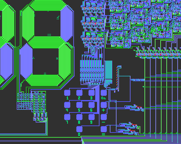
What is Hutton32?
You’ve probably heard of Conway’s Game of Life. A system that evolves on a grid based on the state of its neighbors is called a cellular automaton. There’s a powerful software that simulates cellular automata, including the Game of Life, incredibly fast; it’s called Golly. Hutton32 is also a cellular automaton rule (a type of von Neumann cellular automaton). Golly comes with some demos, and Hutton32 was originally designed to create self-replicating machines faster. There’s also an automaton for simulating digital circuits called Wireworld, and Golly comes with a cool Wireworld prime number calculator. So to get into digital circuits with Golly, one would logically use Wireworld, but the signals in Wireworld are not continuous and you have to deal with “phase differences,” just like the Game of Life where signals are not allowed to be out of sync, and debugging is a hassle. So I chose Hutton32, but Hutton32 is different from a typical circuit in that signals can only transmit in one direction along the wires. (Of course, this eliminates the need for components like diodes.)
Click here to see CFY’s tutorial (only in Chinese) on von Neumann automata.
Wires
We use the green arrows inside blue wires as signal carriers. When the signal inside a blue wire reaches the end, it gets decoded:
(Hint: Click on the image to copy the code directly to paste into Golly and run)
The result of the translation is to generate a new arrow/diamond at the end or to perform operations like backspace. These operations are suitable for Hutton32 to make very fast self-replicating machines, which was the original purpose of Hutton32’s development.
Red wires are special wires, and their signals are purple arrows. When a signal in a red wire reaches the end, if the end is a blue/green arrow or a diamond, the blue/green arrow or diamond will disappear, as if it were “eaten.” We can only use the signal from a blue wire to convert it into a red wire signal through a diamond:
Diamonds
Diamonds (called confluent states in wikipedia) have a wide range of uses and can be divided into the following categories:
- Splitter: Must have one input and multiple outputs, also acts as a delay.
- Delay: One input and one output
- AND gate: Must have multiple inputs and one output, also has a delay when there’s an output.
- Crossing: Must have two inputs and two outputs, no delay.
Note that in the following situation, no signal can pass through:
This is a useless state, but if we change the Hutton32 rules, we can use this state to create a small-sized NOT gate!
Signals and Signal Sources
Signals can be divided into two categories: continuous signals and discrete signals. If you want to perform logical operations with discrete signals, you also have to consider phase differences.
Discrete signal:
A discrete signal can also be seen as a clock signal, for example, the one above is a clock signal with a period of 7. (The diamond as a splitter has a one-generation delay.)
Continuous signal:
They can be converted into each other:
- Discrete -> Continuous:
You can use a discrete signal source and an AND gate (a diamond with multiple inputs and one output) to modulate a continuous signal into a discrete signal. - Continuous -> Discrete:
You can directly use the splitter function of a diamond (one input, multiple outputs).
Logic Gates
OR Gate
An OR gate is the simplest: two signals can be directly merged together.
AND Gate
We use one of Hutton32’s diamond’s mechanism as an AND gate: a diamond with multiple inputs and one output is an AND gate.
Dual/triple input AND gate
NOT Gate
A NOT gate is a bit more complex. It cannot be realized with just blue wires and diamonds. A NOT gate must have an output (1) when there is no input signal (0), which means the NOT gate must have its own signal source. Red arrows have the function of eliminating blue arrows, so we can turn the incoming signal into a red arrow to suppress the signal source from emitting a signal, thus realizing a NOT gate. But this only works for discrete signals: because after the red arrow suppresses the signal source, only a discrete signal with a period greater than 5 can be translated back into a forward-moving blue arrow to reconnect the wire. So we can first convert a continuous signal into a discrete signal, and then convert it back to a continuous signal after passing through a red arrow.
This machine is a bit complex, and of course, this kind of NOT gate has a serious delay.
(High/low level working state)
Digital Displays
The classic 7-segment digital display is easy to make in Hutton32 to show numbers. The decoder in the bottom left is made up of some OR gates.
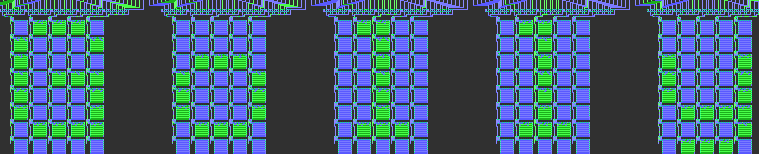
Enlarged view of the decoder in the bottom left:
There are 10 input lines, representing 0-9, and 7 output lines, which light up the corresponding segments.
Well, with these components, the next step is to combine them to implement various digital circuit functions like addition, subtraction, latching, decoding, and more!
(To be continued)